| ▲ Electronics |
A month or so ago, Jarrod Kinsey mentioned that he'd come across this device when he was looking for a means of generating high voltages. In a nutshell, it's a mechanical Marx generator. A Marx generator uses a ladder network of resistors and spark gaps to charge a bank of capacitors in parallel and then discharge them in series to obtain a greatly magnified output voltage. However, this only works when the voltages on individual capacitors are sufficient to jump across a spark gap, which only starts becoming feasible (i.e. repeatable, stable etc.) above about 5kV or so. For lower capacitor voltages, some other means must be used. The Planté machine uses a clever arrangement of a rotating drum commutator and set of fixed contacts to charge capacitors in parallel and discharge them in series. It sounded such a neat idea that I just had to give it a go.
The idea for the machine is quite old, around 1880 or so. The original article where it's described is "Planté's Rheostatic Machine" by Th. du Marcel in Science, Volume 2, Issue 67, pages 478-481, 1881. It's a translation of the original article in La Lumière Electrique, 6th August, 1881. A PDF of the article is available here. There's also a book by Gaston Planté - "Recherches sur l'electricité: de 1859 à 1879", available from http://gallica.bnf.fr/ark:/12148/bpt6k3967k.
It's rather hard to figure out from the paper just what arrangement of contacts he used. There are probably many different ways of achieving this, depending on the voltages used and the required separation of adjacent contacts. Since I'm only using voltages of a few hundred volts, it's possible to place the contacts quite close together. I decided to use a piece of PCB material to form the electrical connections of the rotor, and various bits of springy copper wire as the contacts. I used four capacitors, but it should be possible to extend it to any number Please have a look through all the photos below as your reading, it should help explain things a bit better.
A rectangular piece of PCB material (first photo below) is rotated about its long axis on a lathe. One long edge has the charging contacts (lower edge in photo below), the other long edge has the discharge contacts. The contacts on the PCB are formed from pieces of bent copper wire soldered to the copper board. The contacts on the PCB align with ten springy copper wires held in a terminal block. This provides connections for the input voltage, capacitors, and output.
Please see this PDF for an illustration of the PCB and fixed contacts during both the charge and discharge cycles. During charging, all four capacitors are charged in parallel from the input voltage supply, and the output is disconnected. When the discharge contacts move into place, the input supply is now disconnected, the capacitors are connected in series, and the output is connected. This results in a voltage of four times the input appearing at the output. With a 30V input, this is 120V, easily enough to flash a little neon bulb (see videos later).
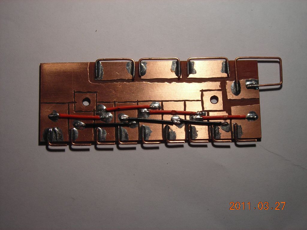 Contact PCB. Bottom - charge. Top - discharge. |
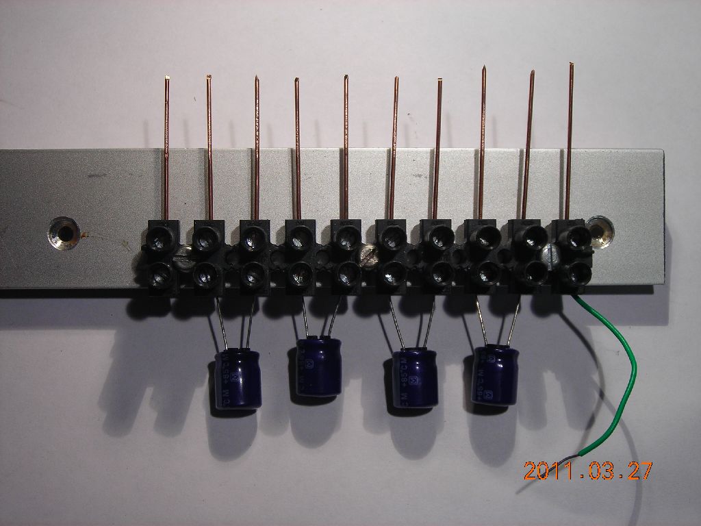 Fixed contacts in terminal block. Four capacitors mounted. |
There is quite a bit of sparking at the contacts, not surpisingly. This could be reduced on the charging cycle by placing a small resistor in series with each capacitor's charging contacts on the rotating PCB and ensuring that the charging contacts remain in contact for long enough. However, there will always be sparking upon the discharge, by its very nature.
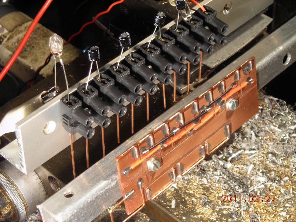
The photos below show the rotor and fixed contacts mounted on my lathe. The terminal block with the fixed contacts is screwed to a piece of aluminium angle held in the toolpost. The rotating PCB is attached to a bit of square aluminium tube held in the 4-jaw chuck.
 |
 |
 |
 |
The videos below show the machine running a neon bulb with different voltages and capacitances.
10μF capacitors, 30V input voltage, 120V output voltage, 18mJ total energy:
2.2μF capacitors, 340V input voltage, 1.36kV output voltage, 891mJ total energy (note purple colour of the neon flash instead of orange):
This sort of machine could probably be turned into a very robust "brute force" machine for generating high-voltage pulses, especially when proper HV caps aren't available (which was Jarrod's original motive). A bank of twenty 400V capacitors, which are commonly found in computer PSUs, could generate about 8kV pulses. There are obviously problems with sparking at contacts, but this could be overcome by submersion in oil, SF6 or similar.
| ▲ Electronics |