| ▲ Electronics |
I needed a small current-sense resistor for a boost converter circuit. Low-value resistors (in the 0.1Ω range) are a wee bit hard to come by, so I made my own from a small piece of Constantan resistance wire.
The resistance wire is 0.35mm diameter, and the total length of about 2.7cm (determined by trial and error). It is pulse arc welded to two pieces of 0.8mm copper wire which serve as lead-in wires (the melting points of Constantan and copper are very close, so they form a decent weld). The whole lot was potted in some quick-setting cement (pure cement, no sand) in a makeshift two-part mould.
The end result is a 0.116Ω resistor in a reasonably compact package, and reasonably noninductive (the wire is very short, and is doubled back on itself).
An amusing aside about choosing the length of the resistance wire - I had previously calculated, from the resistivity of Constantan and the diameter of the wire I had, that I needed 2.27cm of wire to achieve my desired 0.116Ω resistance. My intention was to cut that length, but for some reason I cut of 2.7cm instead. Furthermore, this shortened by a slight amount when welded to the lead-in wires (the metal "balls up" at the end). So, the end result was a totally random length of wire, yet it happened to have exactly the resistance I was after, to within 1mΩ! How often can that happen?
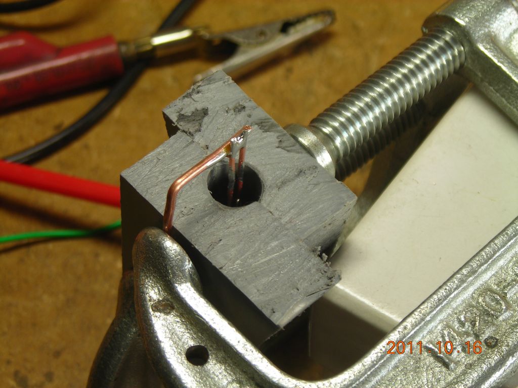
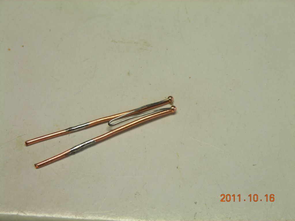 0.35mm constantan wire welded to 0.8mm copper lead-in wires |
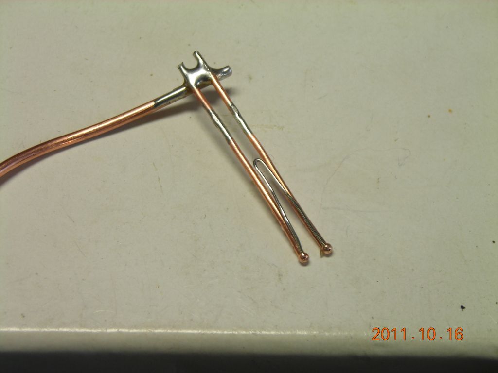 Support wire soldered to lead-in wires. Also ensures a 0.1" pitch. |
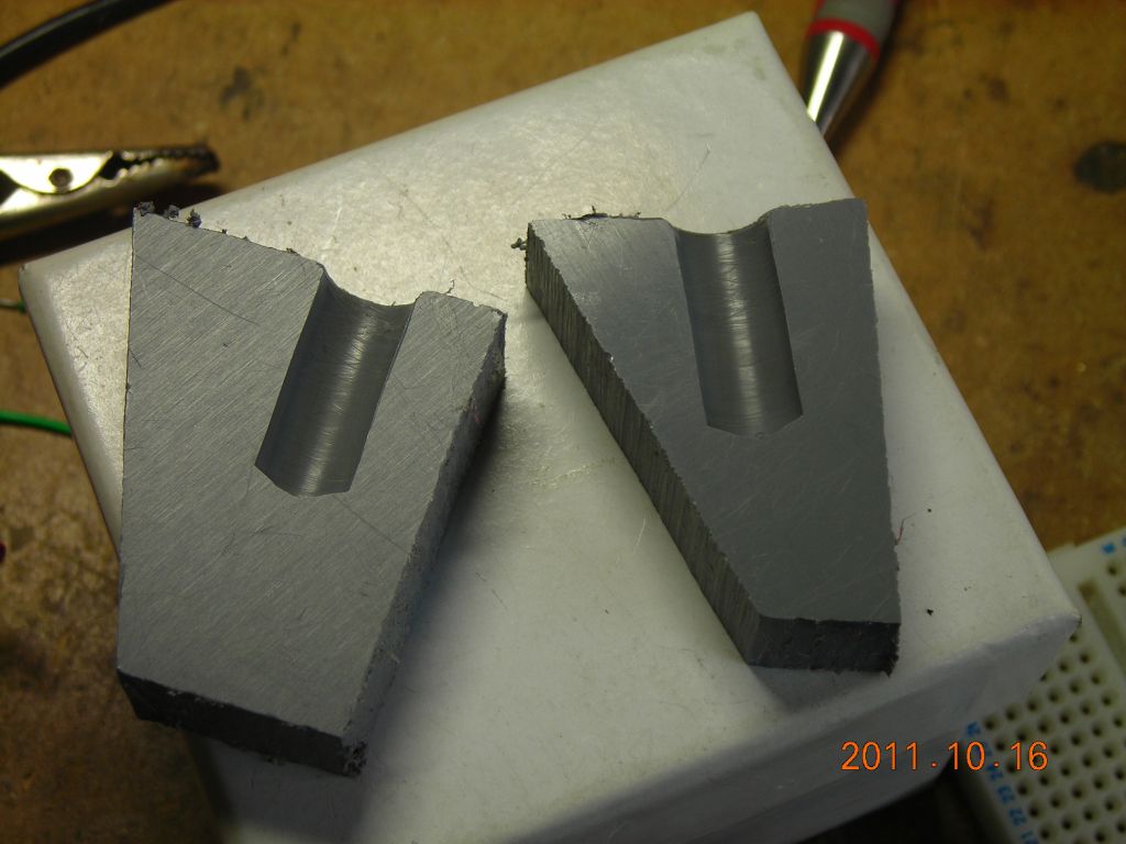 Two-part mould made by drilling into the edge of two plastic sheets clamped together |
 Resistor element in place inside mould |
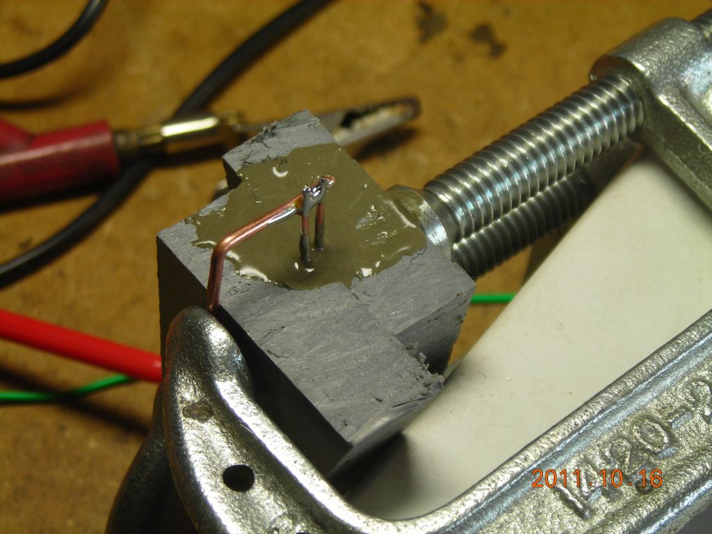 Mould filled with quick-set cement |
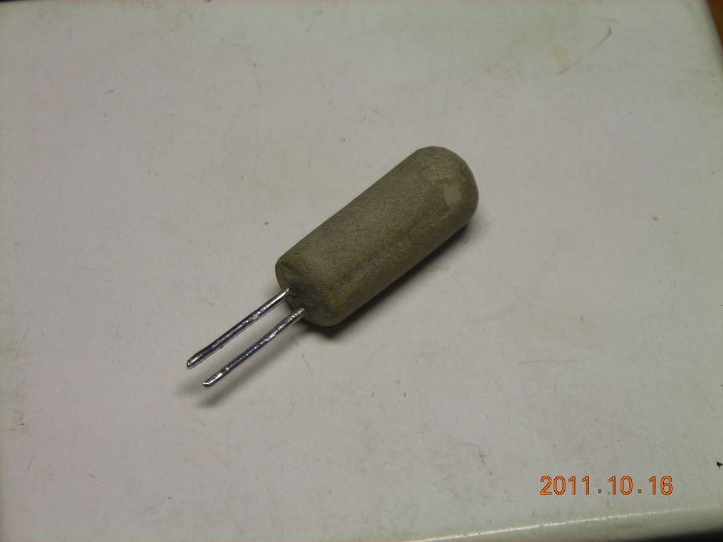 Removed from mould and tidied up |
 Label applied |
| ▲ Electronics |