| ▲ Electronics |
I accept no responsibilty for any damage to equipment caused by following the design shown on this page! If you build it and connect it to your fancy oscilloscope, you do so at your own risk.
Measuring high voltages is tricky, and measuring high-voltage pulses even more so. While a resistive divider may be suitable for DC and low-frequency use, it requires very careful design if it's to be used at high frequencies and with fast pulses. One of the main reasons is the parasitic capacitance of the divider resistors - at high frequencies, the impedance of the parasitic capacitance of the resistor can actually be comparable to the resistance, making measurements inaccurate. Fortunately, instead of a resistive divider, it's possible to build a purely capacitive divider which will work properly from a few kHz to several hundred MHz.
The four papers linked below give good examples of different styles of capacitive dividers. My design is loosely based on them. Note that some of the papers use an additional resistive divider - I have omitted this, partly because I don't fully understand its function.
Here is a PDF drawing of my design. The "upper" (small) capacitor of the divider is formed between the high-voltage input probe, a piece of M3 threaded rod, and a short length of 9mm ID brass tubing (which I've called the "intermediate electrode"). A piece of turned PVC forms the dielectric insulator and the body of the probe. The capacitance can be adjusted from about 0.7pF to 1.7pF simply by screwing the threaded rod out & in.
The "bottom" (large) capacitor is about 1.2nF and is formed from a stack of twelve 100pF chip capacitors soldered in parallel. These are NP0 dielectric (zero temperature coefficient), to avoid any effects that ambient temperature might have. I went for several small capacitors in parallel, rather than one big one, because this will reduce the parasitic inductance.
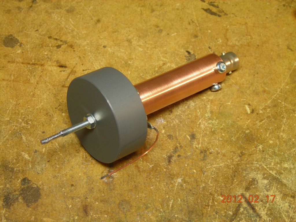
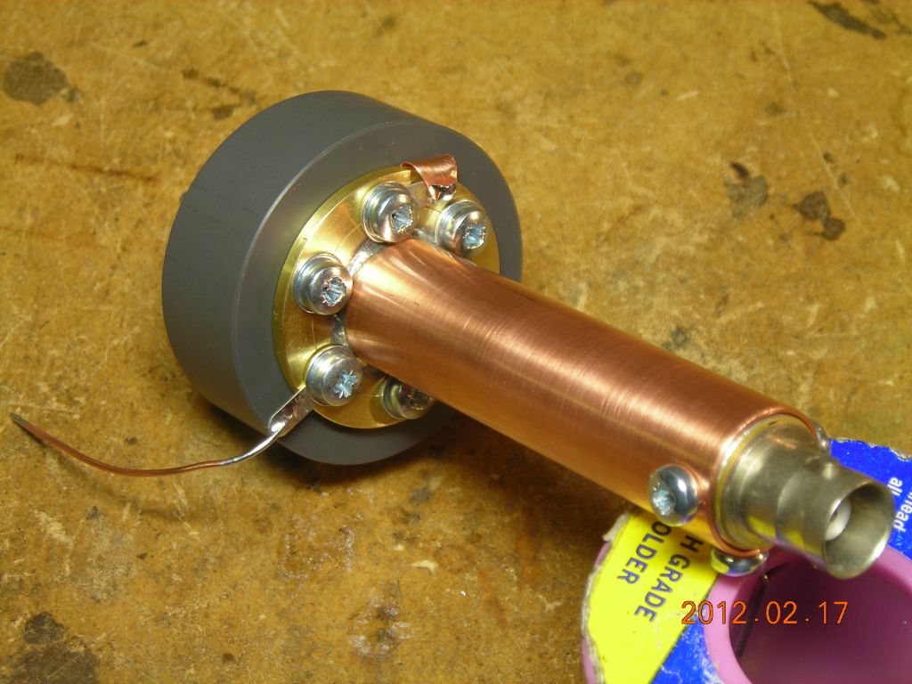
The output terminal, a BNC socket mounted in a brass bushing, is connected across the 1.2nF capacitor. A piece of 15mm copper pipe provides a screened housing for the divider assembly, and is attached to the rear of the PVC body with a brass flange. Note that, in addition to the ground wire coming from the BNC connector, I also have an additional ground connection to a strip of copper foil which passes under the brass flange and is attached with a solder tag to the outside. There's no real reason for this, I just felt that it would provide another conduction path and possible lower parasitic inductance.
The probe is connected directly to the scope input with a 1m length of RG58 cable. The capacitance of the cable (110pF) and the scope input (13pF) add slightly to the lower capacitor of the divider. The 1MΩ input impedance of the scope, along with the 1.2nF lower capacitor of the divider, determines the lower frequency limit of the probe. In practice, it's about 400Hz.
I calibrated the probe by measuring a 40Vp-p 1MHz sinewave signal and adjusting the threaded rod until it produced close to 1000x division. I then checked its ability to record pulses by measuring the output of a small pulse transformer both with the 1000x probe and a normal 10x scope probe. As you can see, there is pretty good agreement between the traces. There is a bit of ringing when the voltage drops rapidly (I think I was running a little neon bulb or several with the pulse transformer output, so this is probably the bulb triggering), probably caused by the inductance of the RG58 cable, but it's not really a problem.
A reader recently pointed me to this document which describes a similar ringing phenomenon, caused by improper termination of the cable.
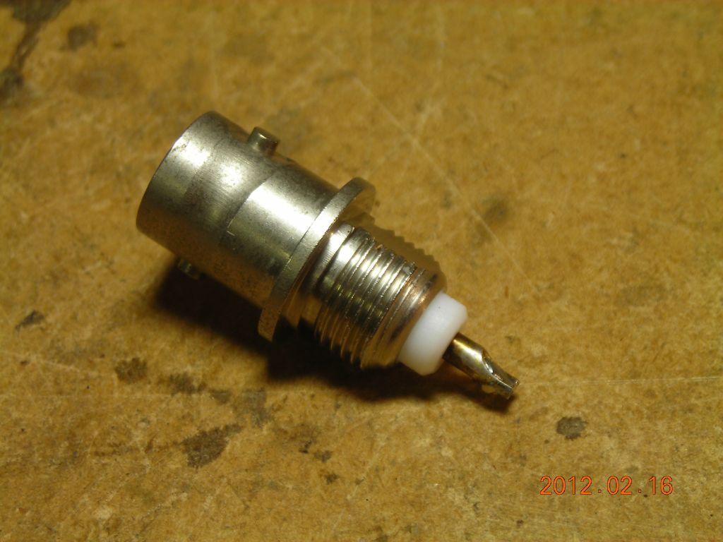 Original BNC socket |
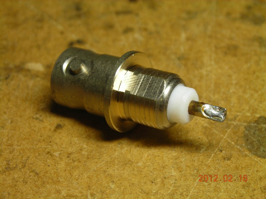 Turned down to a smooth outer diameter |
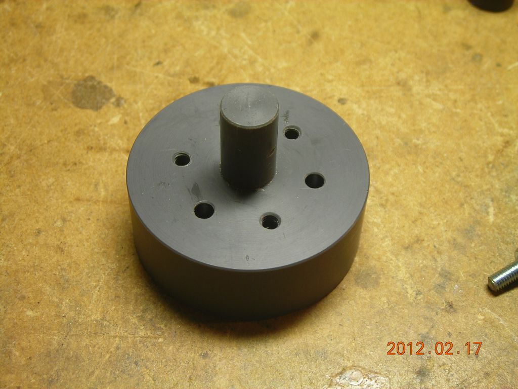 PVC body - intermediate electrode is placed over the protrusion |
 Hole for high-voltage probe (M3 threaded rod) |
 Intermediate electrode, covered in heatshrink |
 Intermediate electrode in place |
 BNC output connector |
 Mounted inside brass bushing with ground wire |
 Housing made from 15mm copper pipe |
 Bottom flange - note groove for additional ground connection |
 Additional ground connection made with copper foil |
 Easiest way of soldering lots of SMD caps in parallel |
 All connections made |
 Housing attached |
 The copper strip is folded up... |
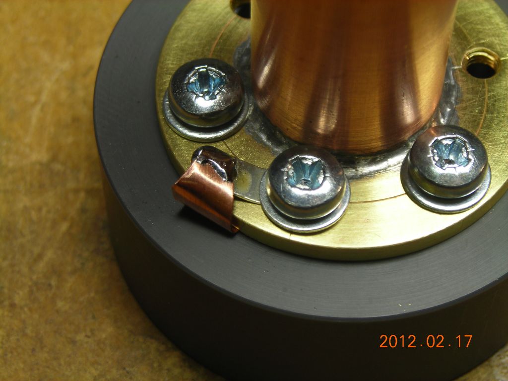 ...and soldered to a tag screwed to the flange |
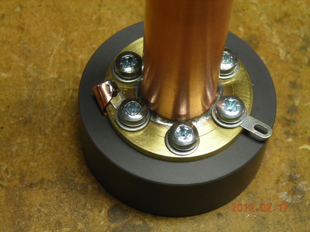 External ground connection is made to another tag on the flange |
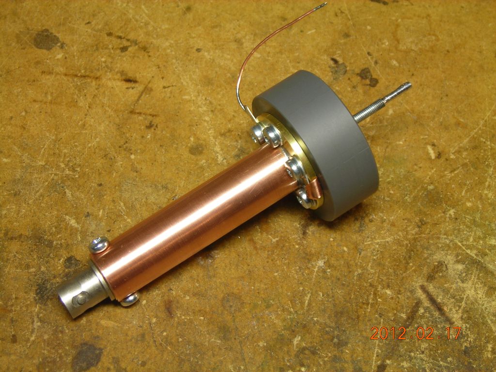 Completed probe |
 |
 |
 Pulse response of probe - note some ringing at the end, but otherwise very good. |
| ▲ Electronics |