| ▲ Electronics |
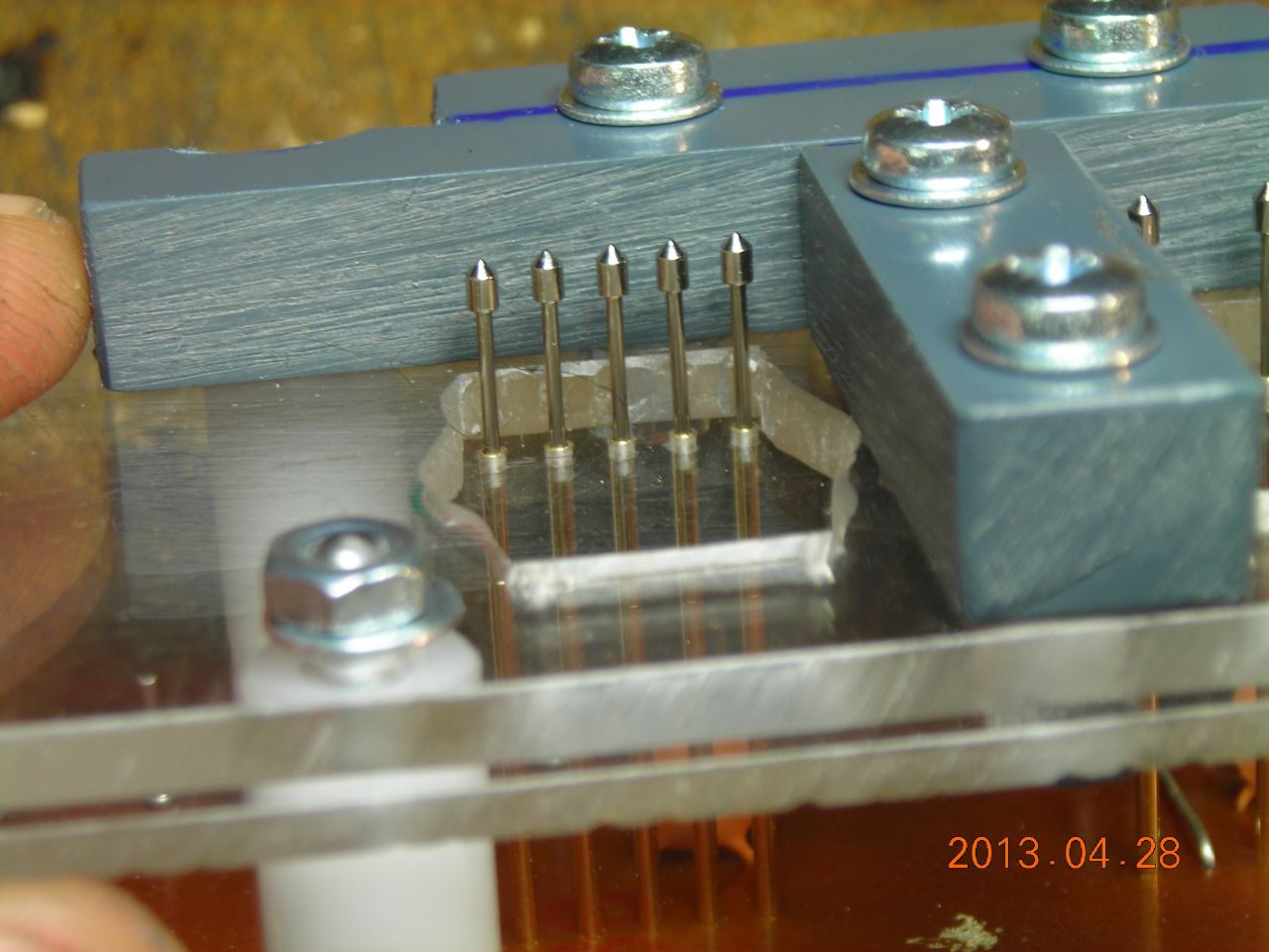
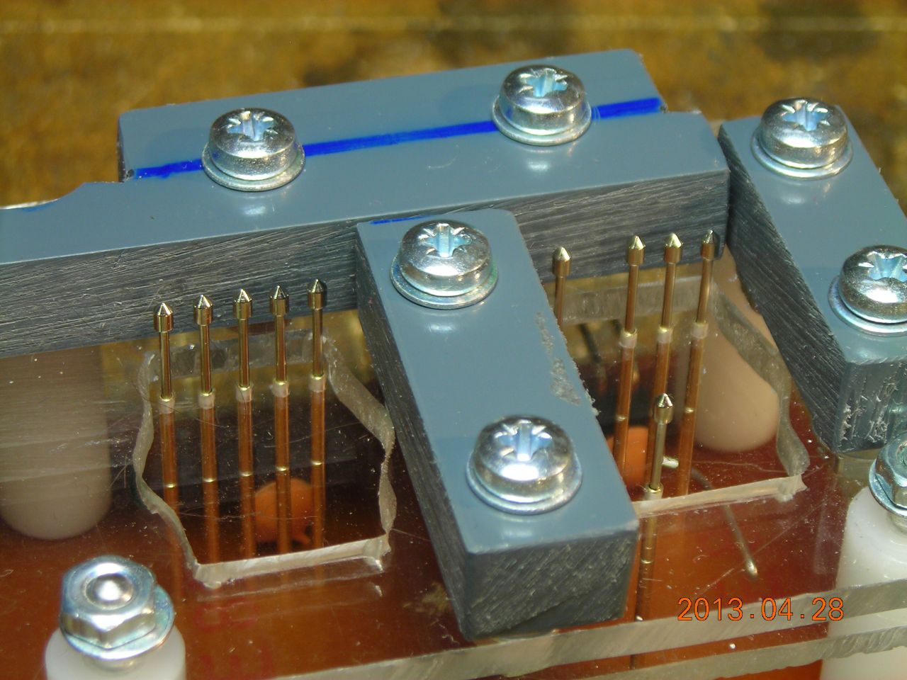
For my rotary encoder module with decoder, I needed a means of quickly programming lots of small PCBs. The standard way of doing this is to make up a jig with spring-loaded pins ("Pogo" pins) which make temporary contact with pads or vias on the PCB.
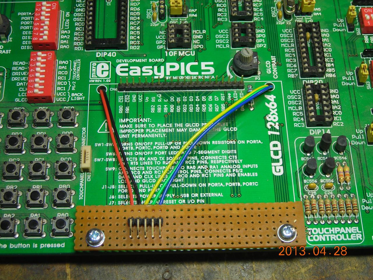
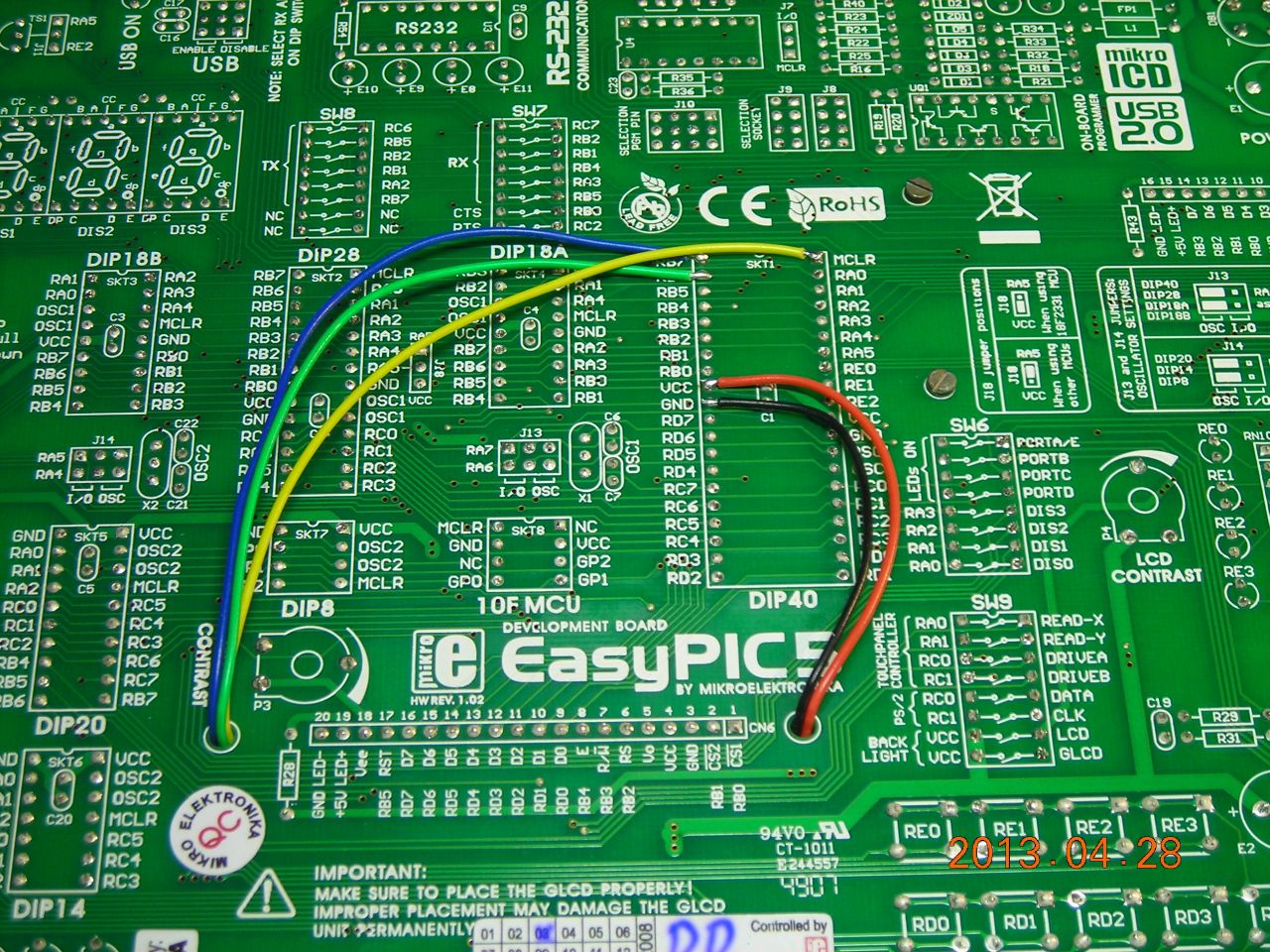
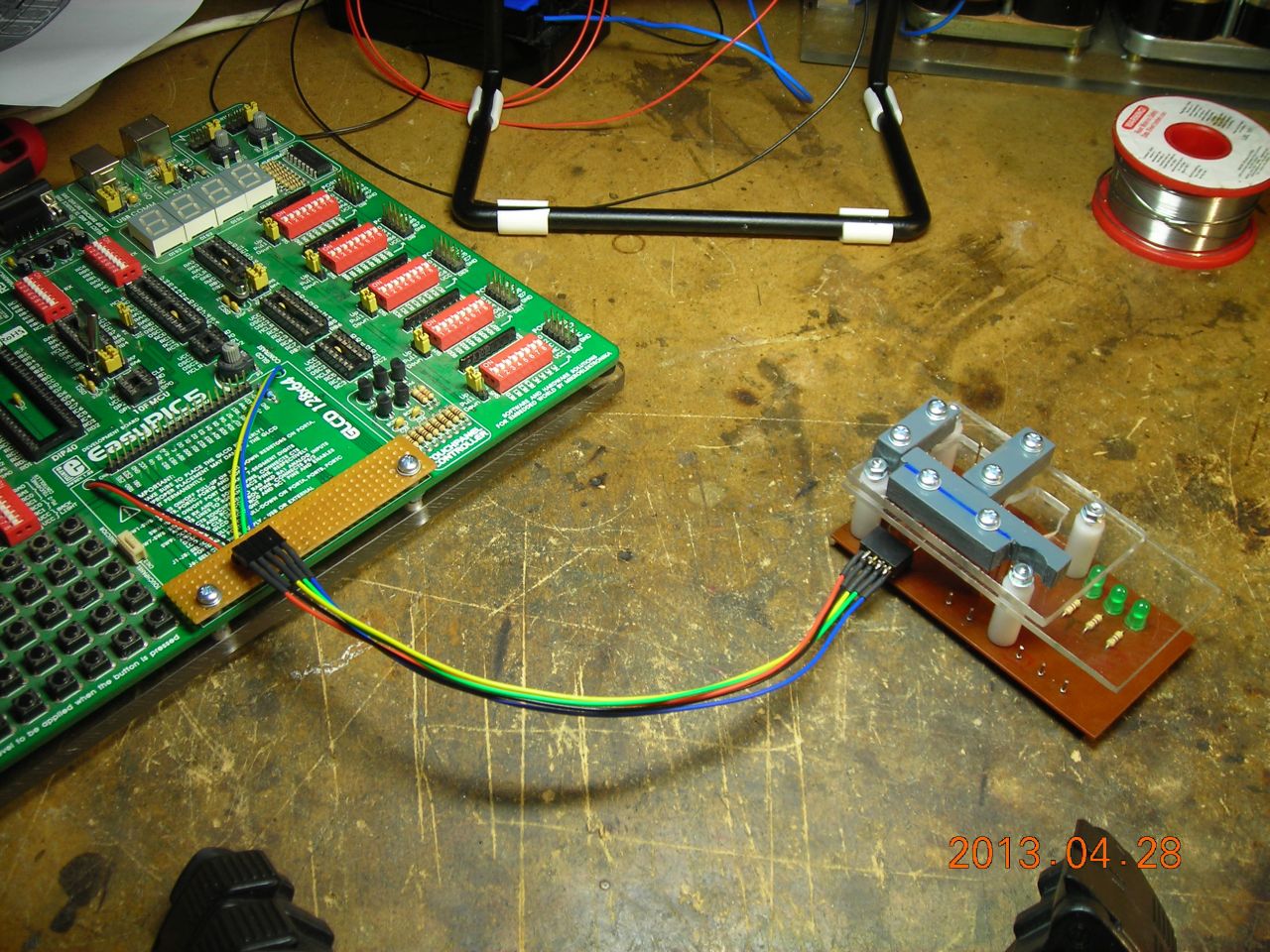
I first added a 5-way ICSP breakout header to my EasyPIC5 dev. board - the connector is located above the GLCD mounting holes and wires are taken from the underside of the 40-pin socket.
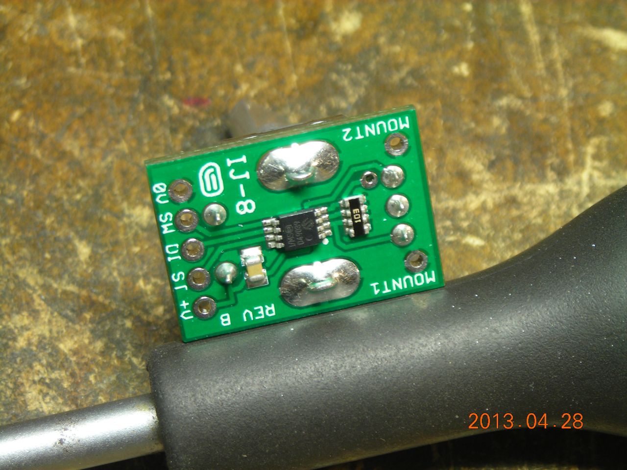
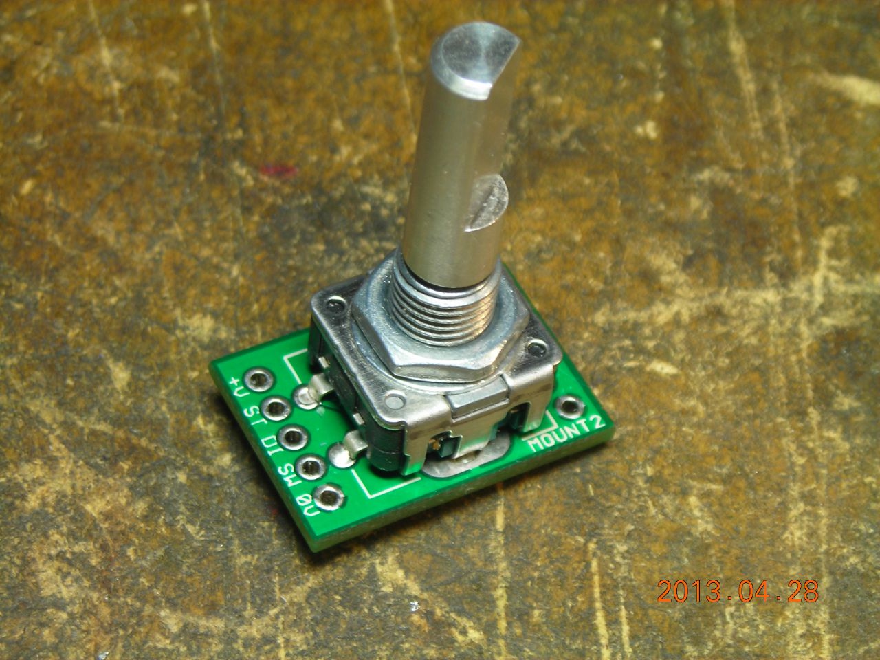
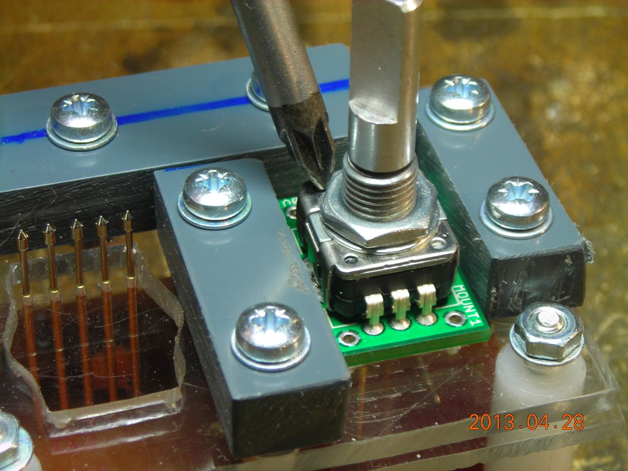
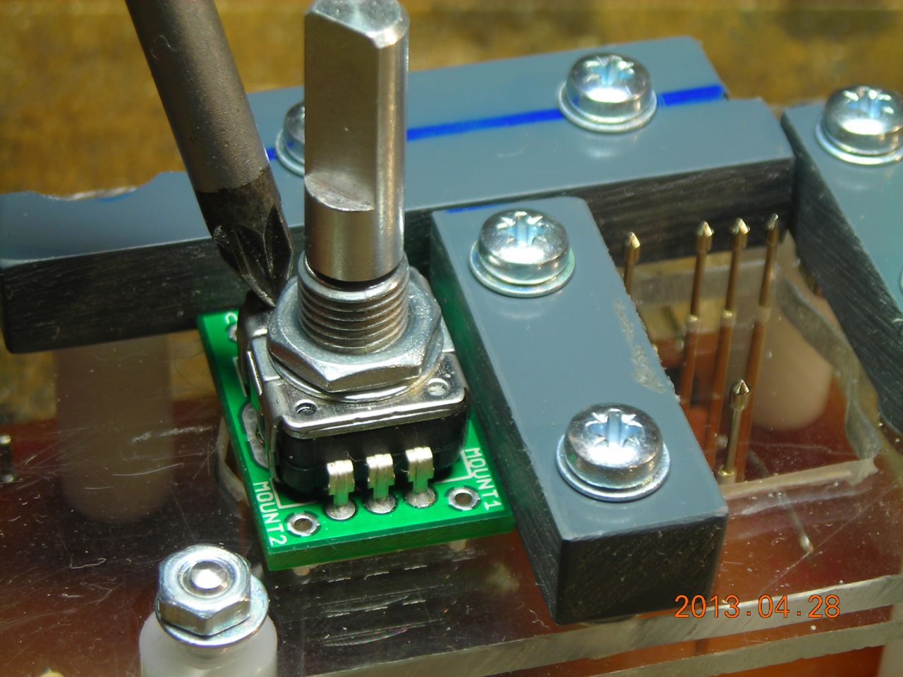
The connections to the module to program are made with pogo pins (http://proto-pic.co.uk/pogo-pins-w-pointed-tip/). Four connections (0V, 5V, data, clock) go to the main outputs on the little module (0V, 5V, step, direction). The VPP connection goes to a via (located just next to the resistor array).
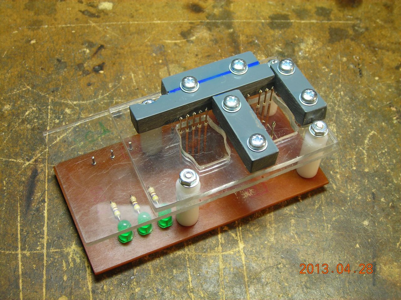
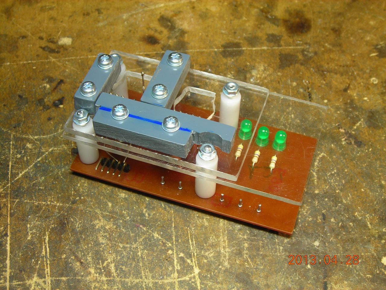
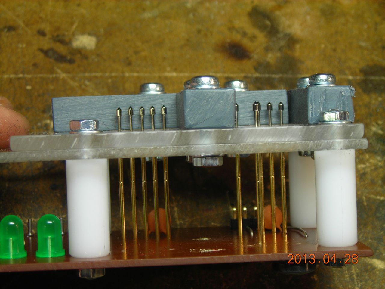
I made up a jig with two positions - one to program the module, and the other to test it. When on the test jig, the status of the step, direction and switch outputs are indicated with LEDs and provide a simple test to check operation. The module is aligned with the pogo pins by some blocks screwed to the top of the pin guide. This isn't actually too critical since the pins can flex a little bit.
It all worked really well and I was able to program around 150 modules in under half an hour.
 |
 |
 |
 |
 |
 |
 |
 |
 |
 |
 |
 |
 |
 |
| ▲ Electronics |