| ▲ Electronics |
Note: This page deals purely with inductors or transformers which are intended to store energy or act as DC chokes. For example - flyback transformers, boost or buck inductors, hysteretic constant-current inductors etc. The guidelines here do not apply to "normal" transformers, forward/push-pull/full bridge converters, or any situation where the transformer is not storing energy (i.e. is acting as a normal transformer). At some point (i.e. once I understand them!) I may put up a page on them as well.
Inductors (and transformers) are pretty useful things (obviously). However, if you try and look up any information on how to properly design an inductor, you will generally be faced with a whole load of equations. This is because most sources assume that you want to determine the correct core size, wire diameter, gapping etc. all before you actually go and purchase a core. Fair enough - I'm sure if you use these sort of design equations regularly then it becomes second nature.
However, the hobbyist is usually faced with the problem from the other end - given a particular core out of the scrap box (e.g. TV flyback, computer PSU etc.) what sort of windings, wire, gap etc. should be used to achieve the desired properties? Preferably, there should also be as few equations as possible!
So, after a few years of making up various inductors for different applications, I decided it was about time that I put down some (hopefully simple) guidelines on how to design an energy-storage inductor for applications such as flyback, buck, boost, etc. converters.
For some background information, see my pages on inductor properties, which demonstrates how inductor parameters vary with gap and turns, and the inductor tester (for measuring saturation current). Another fantastic resource on coil and inductor winding is at the University of Surrey - "Producing wound components". This covers a lot of good theory behind inductor design and is very readable.
1. Thou shalt not saturate the core.
2. Maximum core storage energy is determined entirely by the core and gap configuration and does not depend on the windings.
From your experimenting/simulation, you'll have worked out what inductance and current you need. (You did do this, didn't you? Of course you did.) For the sake of an example, let's suppose you want to make a 85µH inductor which can carry 20A. This is in fact an inductor I made for a PFC power supply.
The maximum stored energy is ½ * L * I^2 which equals 17mJ. We want to work out a core + gap combination which can store at least 17mJ.
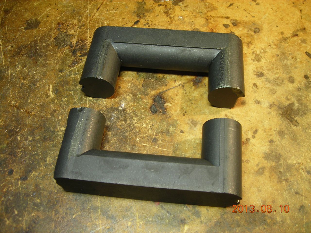
Head off to your scrap box and dig out a likely-looking core. How to choose the size? Guess it! After a few iterations, you'll soon get a feel for roughly how much energy a core can store. Here is the one I chose - it's from a very large flyback transformer (not a TV txfr, this was an "industrial" one). The legs are about 20mm diameter.
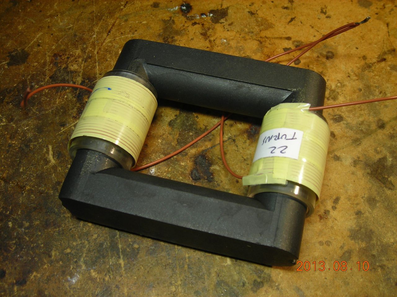
To measure the energy storage capability, we need a test winding. This doesn't have to be anything fancy - pick something that gives you a decent inductance to measure (e.g. at least several hundred µH). Try and have the winding(s) placed over the gap. In this case, since both legs of the core are gapped, the winding is split into two equal halves. There's 22 turns on each leg, giving a total of 44 turns. Again, experience will give you an idea of roughly how many turns to use. When splitting the winding like this, make sure to connect each half the correct way around, otherwise one will cancel out the other!
Connect the test winding to the inductor tester. This will let you determine the saturation current - the point where the current vs. time waveform suddenly starts increasing rapidly as the inductance drops. Measure both the inductance (applied voltage divided by the slope of current vs. time) and saturation current at different core gaps. From these, work out the maximum stored energy and increase the gap until the core+gap can store at least as much energy as originally specified.
I finally settled on a gap of 1.5mm which (for the test winding) resulted in an inductance of 387uH and a saturation current of 21A, resulting in a maximum stored energy of about 82mJ. Since we originally wanted just 17mJ, this should easily be sufficient.
Calculate the inductance factor, denoted AL with units of nH per (turns^2). This is calculated from the expression L=AL*(N^2), or AL=L/(N^2). We have an inductance of 387,000nH and 44 turns, so AL=387,000/(44^2)=200nH/(t^2).
Use the inductance factor to calculate how many turns are required to achieve our original specified inductance. Turns = sqrt(L/AL). We originally wanted 85uH (=85,000nH), so the required turns are about 20 turns.
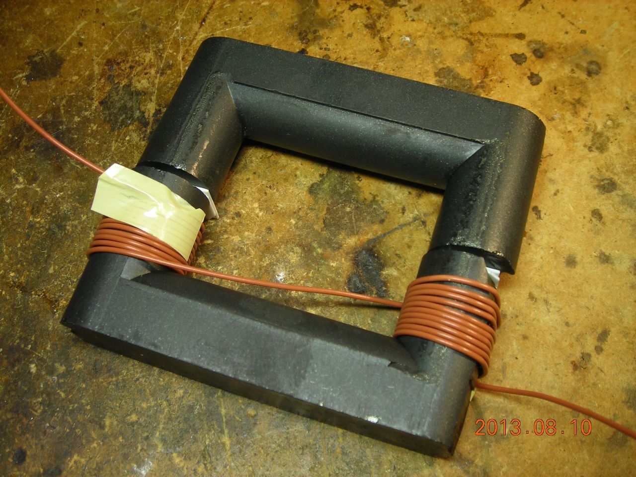
This time, put on the number of turns calculated in step 3 and see how close the inductance is to the desired value. Here's the new test winding, with 10 turns on each leg (total 20) and the same 1.5mm gap:
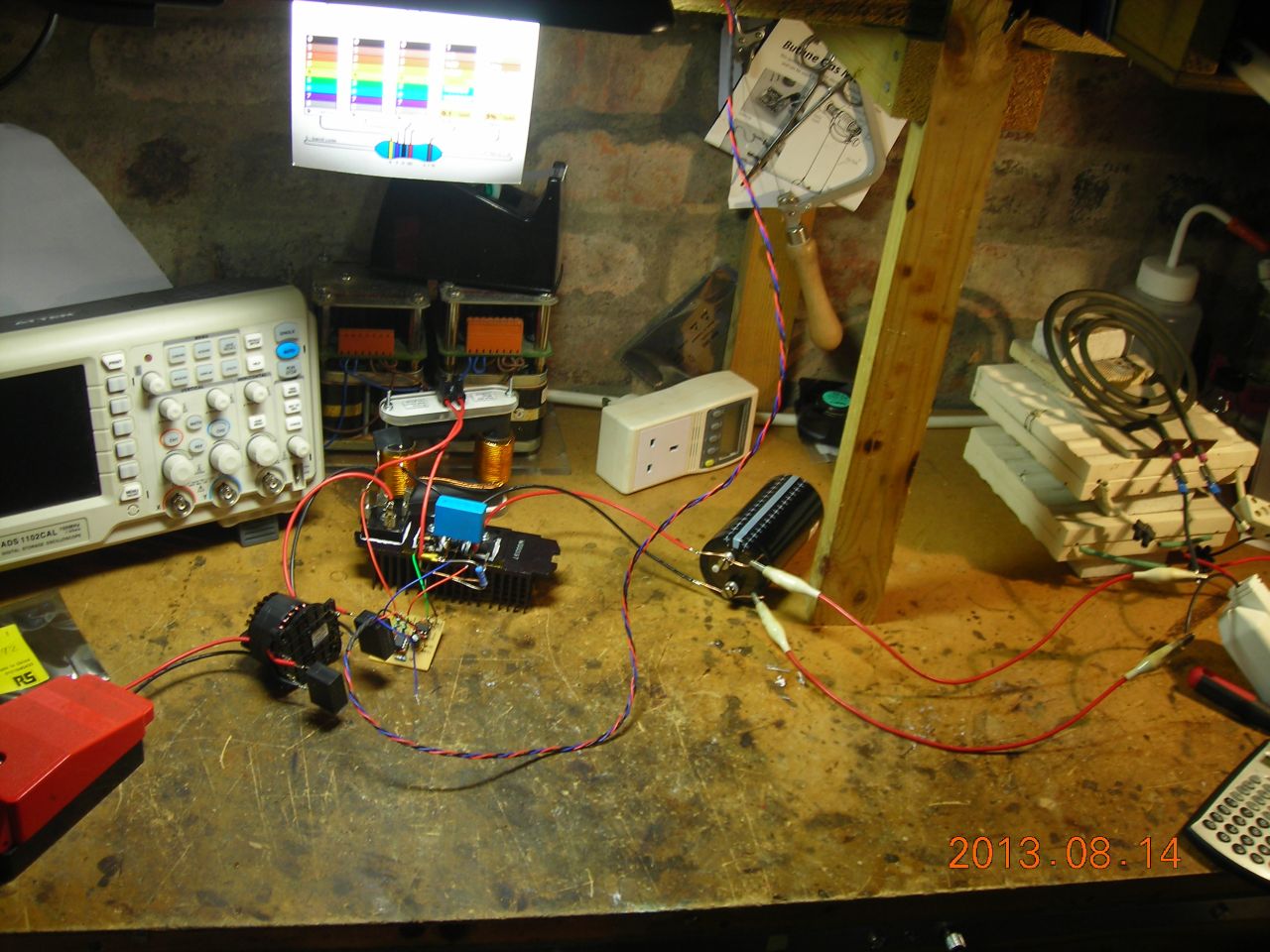
Here it is connected to the tester:

This resulted in an inductance of around 95µH, which is a little bit on the high side, so we could probably gap out the core a bit more (or use slightly fewer turns). Let's see what the inductance is like with the final, "proper" winding.
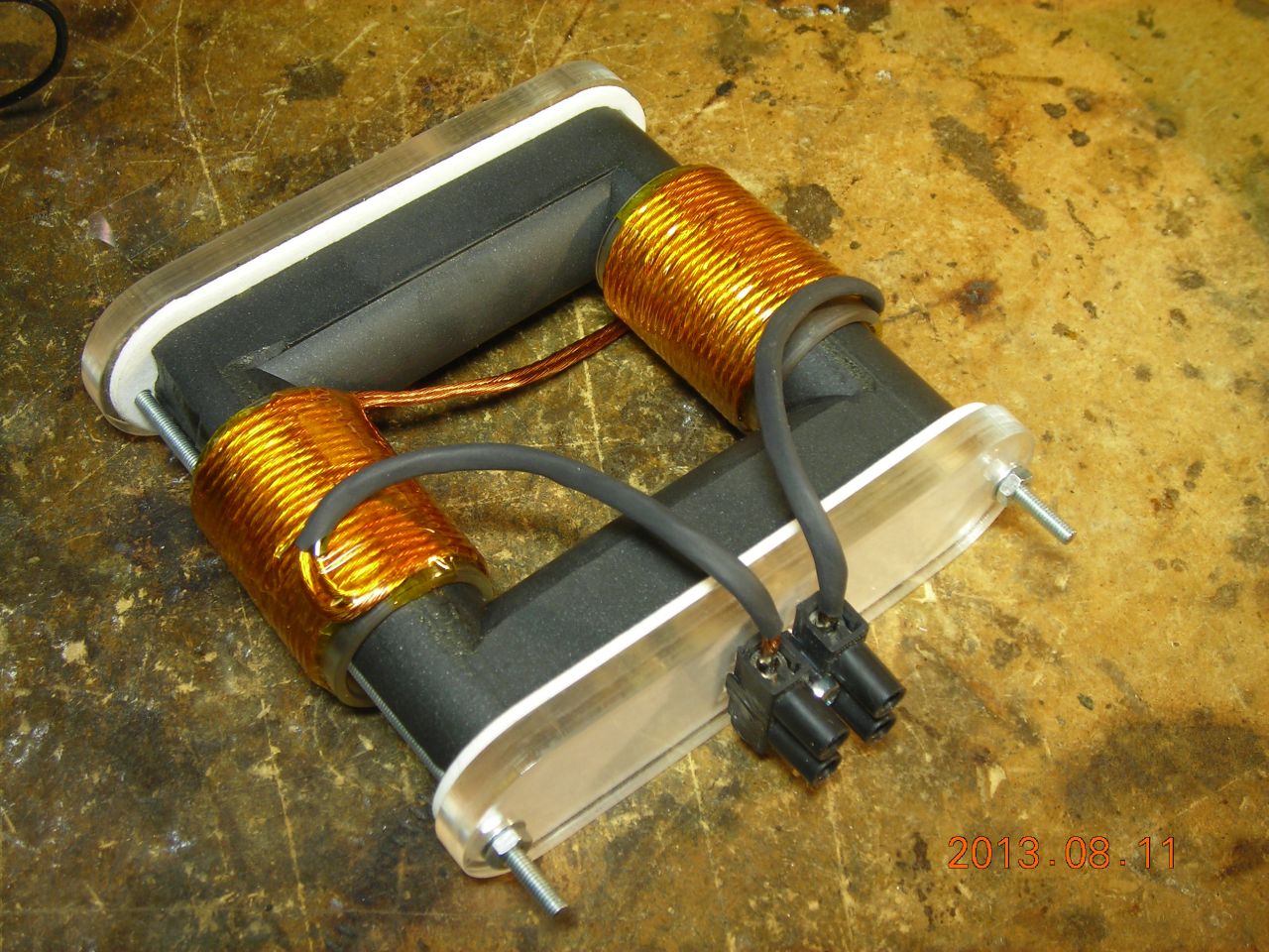
The final winding will need to handle the maximum current, so needs to have a decent cross-sectional area. It's also a good idea to make it from many strands of thinner wire (a Litz winding) to reduce skin effect losses if operating at high frequency. I finally used 40 strands of 0.23mm enamelled wire, wound in two bundles of 20 and then paired together (i.e. to give a total of 20 turns overall). Here's the winding, along with a frame to hold the core together:
Connect it up to the tester yet again:
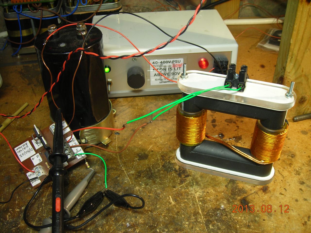
With the 1.5mm gap, the inductance was a bit low at around 50µH (in theory, inductance only depends on the number of turns, but in practice it also varies slightly with the size/shape of the winding and the wire diameter). I found that reducing the gap to 1.25mm gave an inductance of 78µH and a saturation current of 39A. This corresponds to a maximum stored energy of about 60mJ, which gives a safety margin of over 3x, since our original specified maximum energy was only 17mJ.
Hopefully this has given some insight into how to empirically "design" an inductor for a particular application. Trial-and-error is your friend here - you'll often find yourself going back, trying a different gap, different number of windings etc. to settle on a final value.
The actual inductor shown here worked great in the final application. The PFC supply was able to deliver over 1kW at 400V from an input supply anywhere from 100VAC to 230VAC, with a power factor of around 97%. I used the NCP1653 PFC controller, which is a really neat chip.
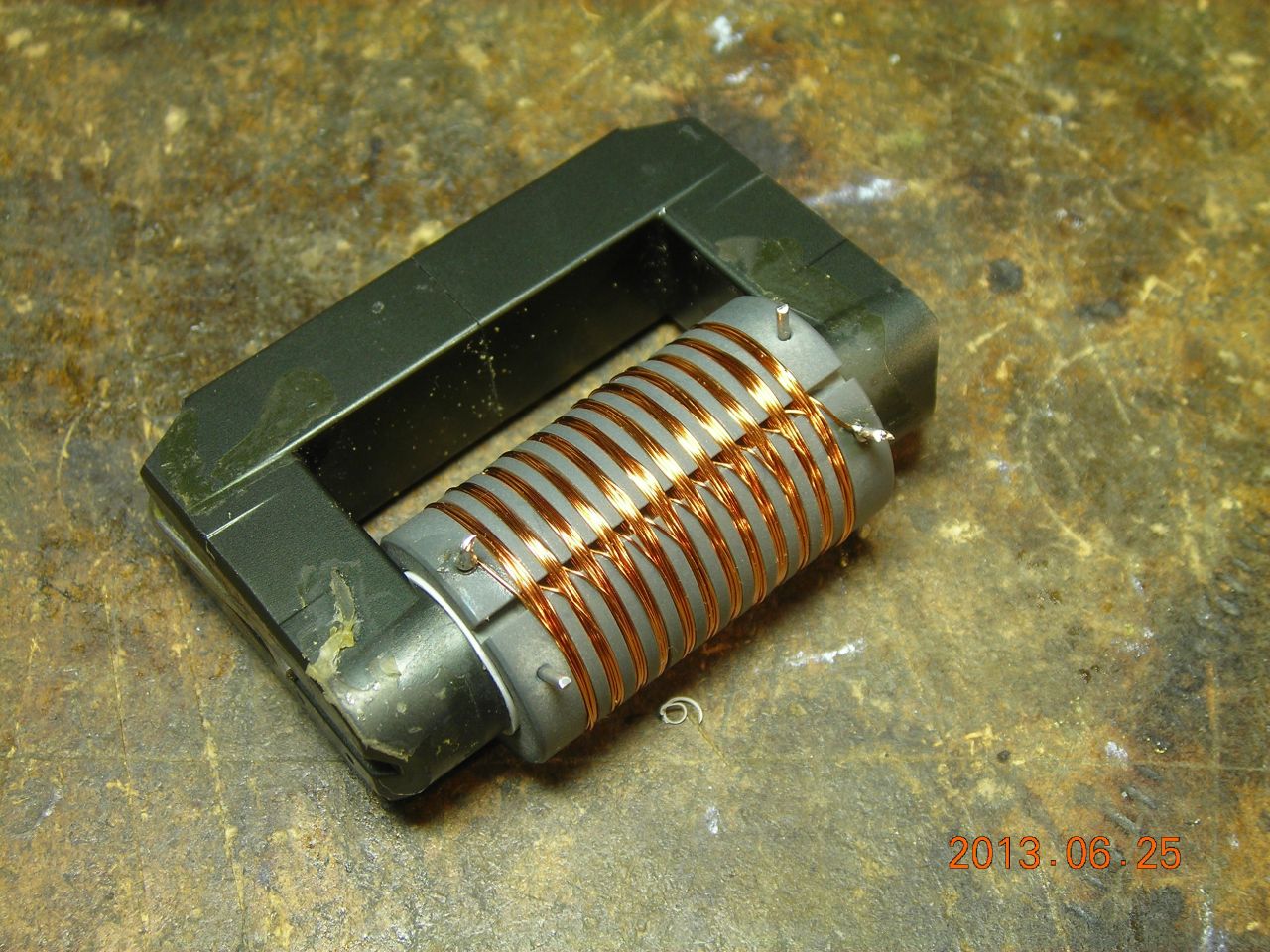
Suppose you want to design a DC smoothing inductor to carry a specified maximum current and you don't care too much about the actual inductance. Again, as an example, I wanted a output smoothing inductor for a hysteretic constant-current supply which could handle at least 300mA and had an inductance of somewhere in the 20-100mH range. I found a nice TV flyback core which already had a 0.5mm gap in one leg.
First, put on a test winding (18 turns) and measure the saturation current. I got 9.4A. Multiply these together to give a saturation ampere*turns of 170A*t. We want to carry 300mA (0.3A), so the number of turns which would saturate at 0.3A is 170/0.3=560 turns. Let's go for say 400 turns which will increase the saturation current further.
As it turned out, with the bobbin I made, I could only fit on 360 turns. This gave a saturation current of 480mA and an inductance of 45mH - perfect! Here's the result:
The reason for the sectional winding is to reduce the parasitic capacitance - it's a long story, but a high parasitic capacitance coupled a lot of noise through to the output. Splitting the winding into sections like this dramatically reduces the capacitance. Here is a comparison between the previous inductor I'd been using (just a single winding on an iron core) and the new, low-capacitance inductor. The new inductor has nearly zero spiking on the output when the MOSFET in the supply switches.
| ▲ Electronics |