| ▲ Mechanical |
I first started thinking about this back around the 18th of May. Back then, I was considering how to make/improvise a powerful enough steam engine that could run a generator to power the house. I'm really attracted by steam power; all you need is water and wood and you're all set. No fossil CO2 emissions whatsoever!
But 2kW steam engines are expensive, and the boilers are even more expensive. So how would I make one?
Let's see, what do I need. I need a crankshaft. I need a piston and connecting rod. I need a cylinder. I need some sort of valve mechanism. Hmmm......doesn't that sound suspicously like an internal combustion (IC) engine? This was my idea: would it be possible to convert an old IC engine into a single-acting steam engine? I figured that it would be possible but the valves are still a problem.
In an overhead-cam IC engine a chain runs from the crankshaft to one or two camshafts mounted on top of the cylinder head. The camshaft actuates the inlet and exhaust valves.What if you removed the entire cylinder head and replaced it with a plate with lots of rotary valves that are turned by the chain from the crankshaft? I decided to try and build a "proof of concept" engine using an old model aeroplane engine. The piston was bust, but there was still a crankshaft, cylinder and conrod.
I initially tried to figure out if a single rotary valve could control both the inlet and exhaust cycles but soon found out this wasn't possible. You need two separate valves to control the inlet and exhaust cycles.
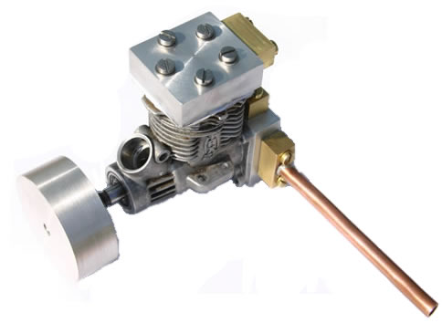
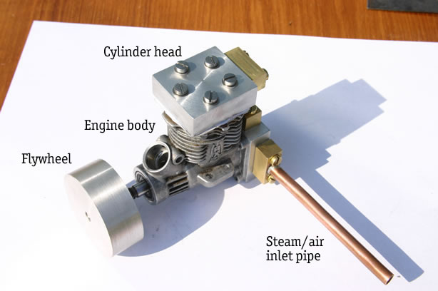
Here's a few shots of the entire engine.
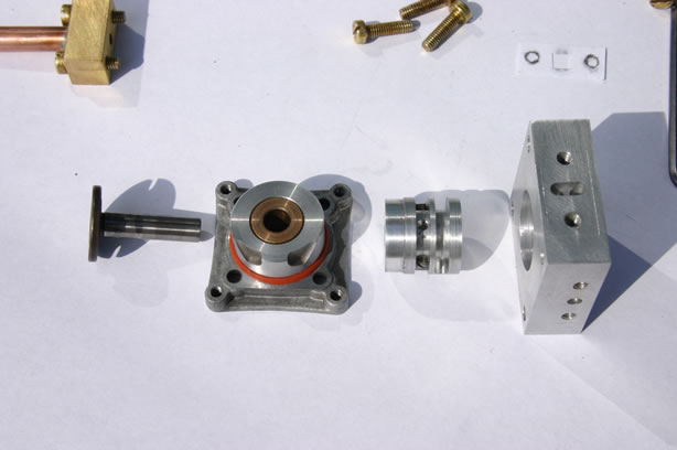
Right, let's start from the beginning. Here's a picture of the original engine exploded. I bought this for £4 from a trade show in Wembley last year. One stall had a huge box of "almost" working model aeroplane engines, all at around £5! Quite a steal.
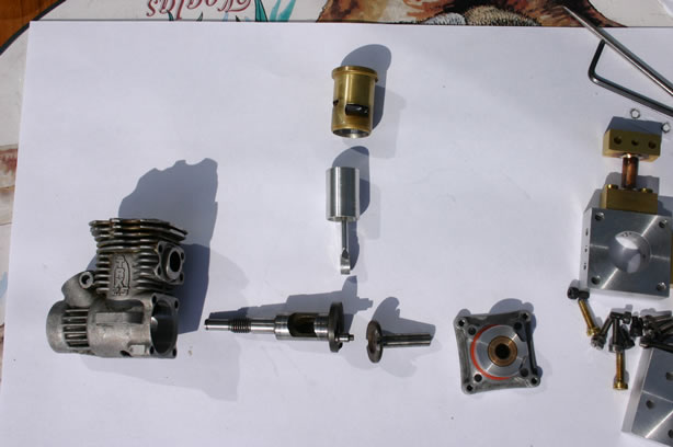
You can see the engine body, the crankshaft, piston assembly, cylinder liner, crankshaft extension and rear bearing. The crankshaft is supported by two ball bearings inside the engine body at the front. The crankshaft extension is supported by a bronze bush.
I had to make a new piston since the old one had cracked around the gudgeon pin. Here's a few shots of the new & old pistons.

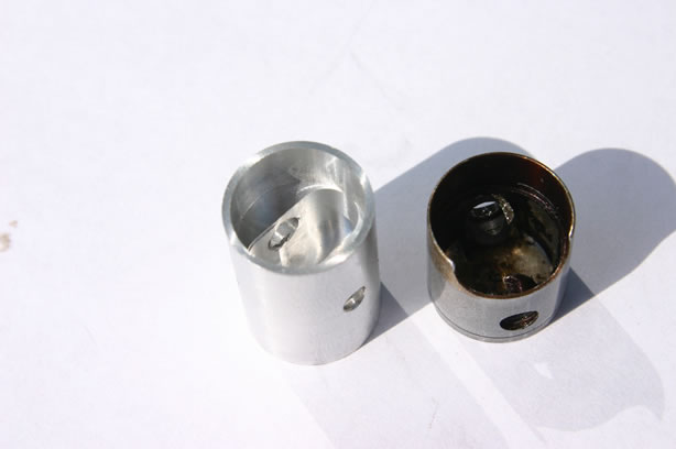
The new piston was made almost entirely using the CNC rotary table mounted on the Sherline mill. I cannot say enough how wonderful that little machine is! You can see that the new piston is considerably longer than the old one; this is to prevent the piston uncovering the original inlet & exhaust ports that had been cut into the cylinder liner. It means the piston protudes from the liner at TDC, but that can be got around. I didn't want to machine a new cylinder liner too!
Here's the crankshaft, cylinder and cylinder liner assembled.
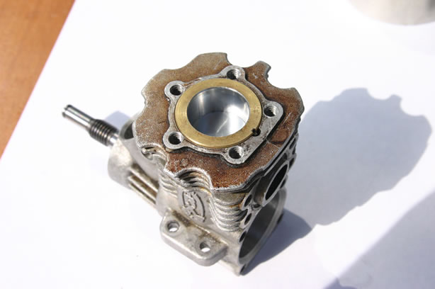
Next, the cylinder head. You can see 5 holes around the edge of the liner where the original cylinder head (with the glow plug) would've been attached. How on earth do I drill 5 holes on a nice pentagon?!? Again, the CNC mill to the rescue; a little bit of trigonometry and I had the coordinates of each point. I used the mill to centerdrill each hole and also to mill a recess in the middle of the head to clear the extra-long piston.
I drilled a hole on the side of the cylinder head to allow steam/air to enter/leave the cylinder head. Again, I did this with the mill to locate the holes.
Here's the results.
Now here's a picture of the crankshaft extension and the rotary valve components. More about this later.
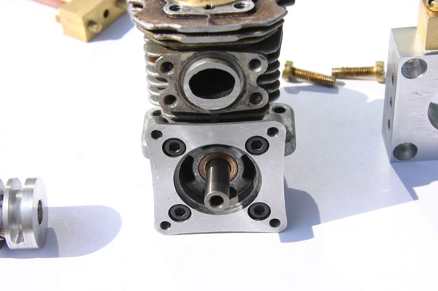
Here's the crankshaft extension and rear bearing assembled on to the engine body.
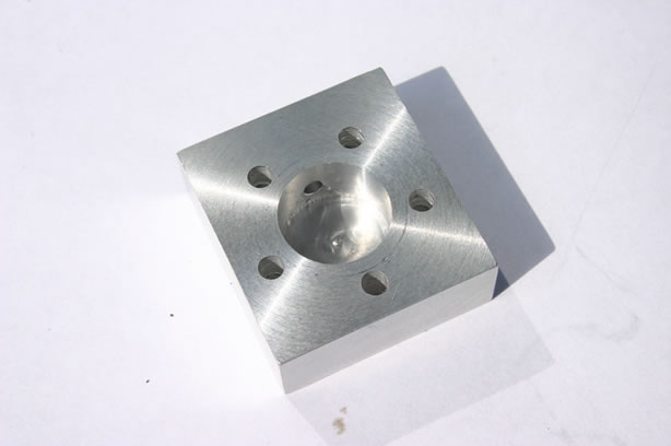
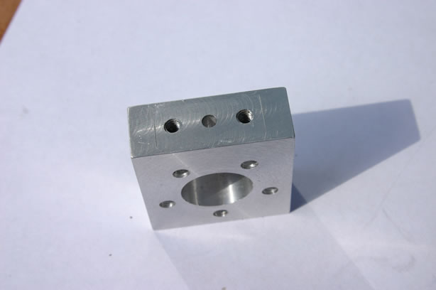
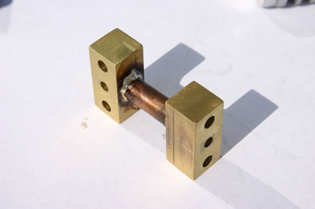
Here's a picture of the valve body and connecting pipes. Steam/air enters through the left-hand pipe. The cylinder connection is on the top and the exhaust port is on the right. There's a closeup of this below.

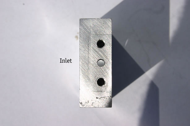
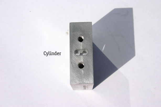
Here's the valve body, looking inside it. You can see the single inlet port, the two cylinder ports (these are connected by a milled channel on the outside of the valve body, see later) and the exhaust port.
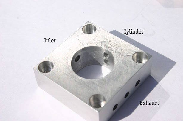
The following three pictures are looking into the inlet, cylinder and exhaust ports. Note the positioning of the inlet and exhaust ports relative to the sides of the valve body. In all the pictures, the valve body is attached to the engine with the engine body on the left. Note how the inlet port lines up with the right-hand cylinder port and how the exhaust port lines up with the left-hand cylinder port.

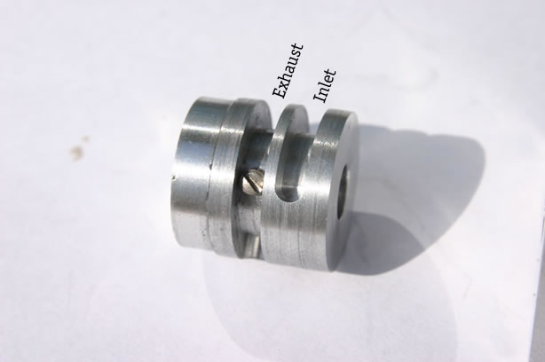
Now here's the valve rotor. It fits inside the valve body and is rotated by the crankshaft extension. The two milled grooves (which only extend part of the way around the rotor) open and close the inlet and exhaust ports at different points in the cycle. The groove on the right controls the inlet port, the groove on the left controls the exhaust port. The "perfect" cycle would be to connect the inlet port to the cylinder port for one half cycle and connect the cylinder port to the exhaust port to the next half cycle.
Note: this rotor is actually cut wrongly! Turns out, it opens the exhaust port 1/2 way through the inlet stroke and opens the inlet port 1/2 way through the exhaust stroke. Which means the engine will still run, but pretty slowly. I'm planning on cutting a new rotor. The grooves were machined on the CNC rotary table on the Sherline mill, again! The table was mounted with its axis horizontal and the rotor held in a chuck on the rotary table.
Another note: You'll probably have noticed that both the rotor and the valve body are made of aluminium. Yeah, I know it ain't great, but I reckoned it would cause less wear than if I made it out of, say, brass. Since this is only a proof of concept model, I'm not too worried. Light oil seems to help and once the engine's run on its own for a while, it smooths out.
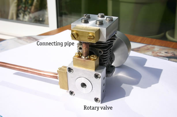
Here's the connecting pipe. The right-hand end connects to the top of the valve body and the left-hand end connects to the cylinder head.
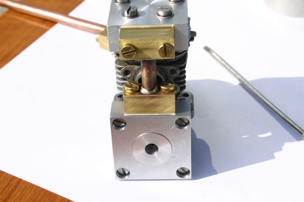
Here's the rotor, valve housing, connecting pipe and cylinder head all mounted on the engine body. The trick is to get the valve body located first so the rotor turns smoothly and then tighten up all the other screws. I've used paper gaskets in all the joints.
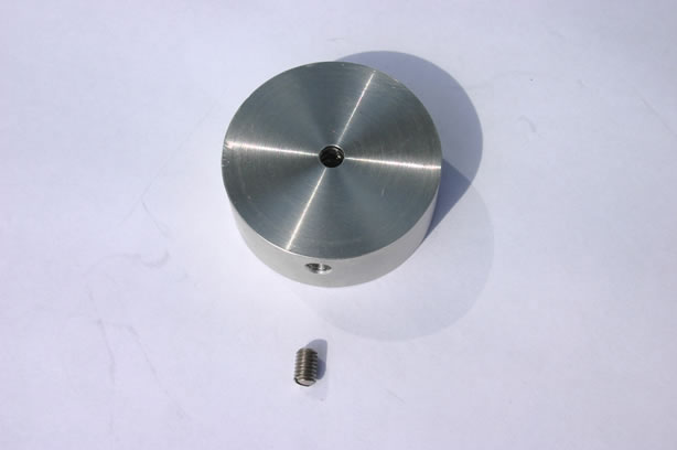
Finally, I had to make a flywheel. I cast one in pewter and turned it down. Pewter gives a surprisingly good finish when turned in the lathe.
And that's us back to where we started at the top of the page!
I tried running it on compressed air at around 50psi and, after a bit of encouragement, it took off! Well, not exactly took off, but it did run. Maybe at about 2 revolutions per second. As I mentioned above, the wonky valve rotor can't be helping its cause any. I tried putting some oil around the valve rotor and that seemed to speed things up a little bit. Quite a bit of air leaks out from around the rotor (I had to sand it down quite a bit for it to turn smoothly inside the valve body); I might machine a brass plate to fit over the end to trap the air.
So it works! Hooray! I've still to make another rotor, possibly a brass plate and a nice wooden stand ;-)
| ▲ Mechanical |