| ▲ Homebuilt CO2 lasers |
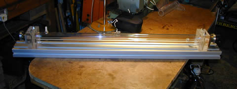
Bought a length of aluminium section from RS. Has T-slots running the length of it so ideal for an optical bench.
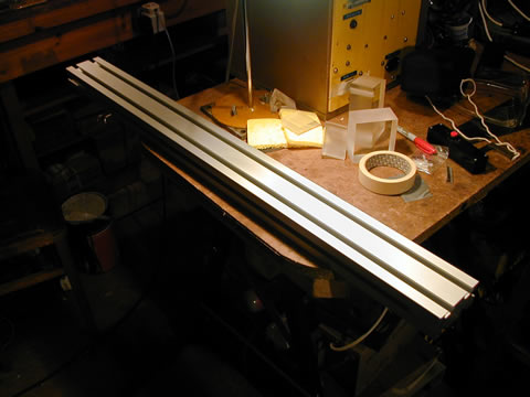
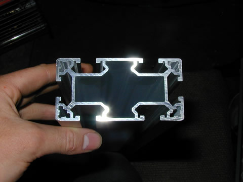
(RS part no: 261-1949 in case you want to buy some. They also have longer sections. Check out http://rswww.com). Started turning down a perspex offcut from university that will end up as the two heads for the laser.
That's a homemade "vise" on the faceplate to hold the perspex block.
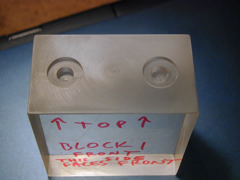
And here's one of the finished heads:
Turned down other head blank in morning. Milled holes for bolts and drilled them through at night.
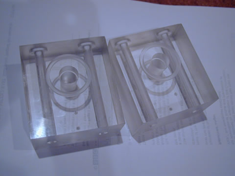
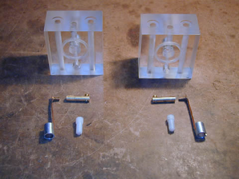
The two finished blanks
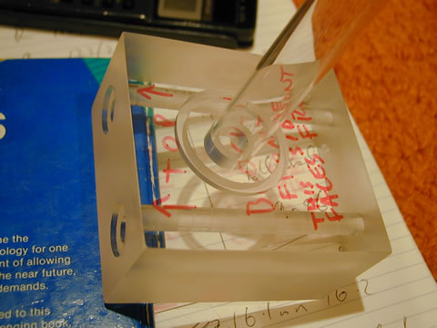
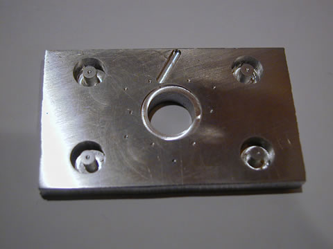
Preparing to mill the guide holes and washer recesses in the head, using a Sherline CNC milling machine.
Finished milling the holes
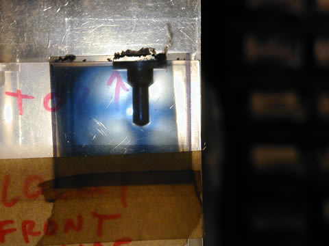
This was drilling the holes for the bolts. I stuck two polaroids to the block so you can see the stress patterns produced by the drill.
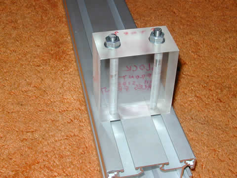
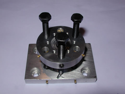
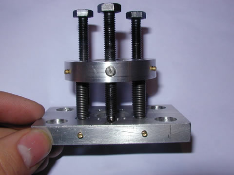
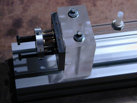
The finished head bolted to the base. It's to be hoped there's enough room between the bolts to fit the plasma tube in!
Milled out other head blank and drilled the holes for it. Looks exactly like above!
Going away for 10 days tomorrow so nothing will happen in the meantime.
Back from holiday and got glass tube at last! It's 16mm OD.
Milled out recesses for both the glass plasma tube and the cooling jacket (have ordered from RS and will get tomorrow). Pic below.
Got the acrylic pipe from RS today. Milled out the recesses in the other head and amazingly they are at exactly the same height from the base! Whew, that's a relief. But that's what you can do with a CNC mill! Next will be gas & electrical conns, then I have to worry about the mirror mounts. That's where it gets exciting!
Bored out a hole using the lathe in each of the heads to allow a clear passage of the infrared.
Drilled holes for the electrode pillar and the gas connection. Pictures tomorrow.
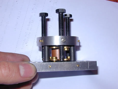
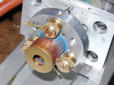
Made 2x electrodes, 2x gas connections and 2x electrode pillars. In pic below, they are: electrodes - shiny aluminium pipe with copper foil strip & soldered bolt attached. Gas connections - parts of a nylon bolt drilled and turned down. Electrode pillars - brass bars with setscrew at one end.
Pic of how the electrodes etc are assembled:
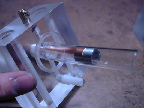
The bolt on the copper foil threads into the brass pillar which provides a seal as well as a mechanical/electrical connection to "the outside world". A seal will be formed by lots of silicone RTV rubber that will be injected into the space between the plasma tube and the cooling jacket.
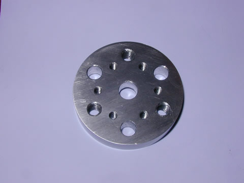
The CNC mill came into its own today! I made the "top" plate of one of the mirror mounts. Used the CNC mill to centerdrill the various holes required. Here's the results! Front side of mirror plate:

Rear side:
And with the various screws in place:
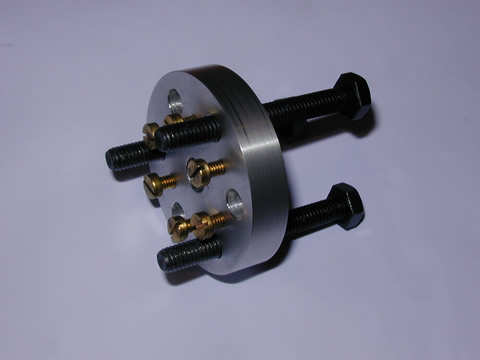
The big black screws are the adjustment screws (they're joogly just now but that'll be fixed). The brass screws hold on a brass plate that is soldered to a 15mm copper tube to seal the whole mirror mount. Right, "poor explanation" I hear you say; well, hopefully it'll become clearer as things progress! I'll put up plenty of pictures.
Half-finished one base plate of the mirror mounts:
That horrible-looking slash at the top was intentional; for a proper kinematic mirror mount, you need a hole, a slot, and a flat. That's the slot.
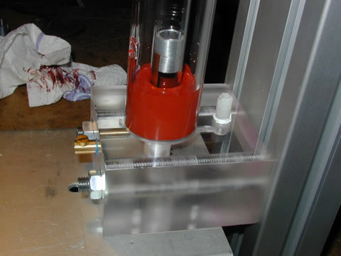
Finished (well, not quite, but it stays together and tilts properly) one mirror mount.
See those little grubscrews spaced around the edge of the top disc? Well, they press on a little chunk of nylon, which in turn presses against the adjustment screw to prevent it joogling from side to side yet still be adjustable. I have the technician at university to thank for this idea!
A closeup of the mount. Note the ball bearing under the screw at the front. Will probably need stronger springs but will see what happens.
Milled out two little plates that will press on the O-rings.
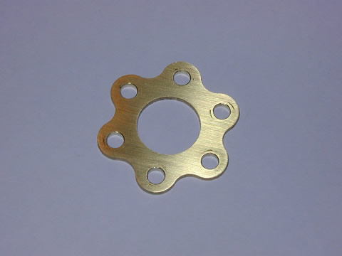
Flower power!
The mirrors arrived from Laser Research Optics today! Wonderful. 10m ROC enhanced Si for the total reflector ($70) and 80% reflectivity ZnSe OC ($90). Very good service!
One of the completed mirror mounts (finally!). A slight change of design - that is a section of 15mm copper plumbing pipe in the center. Two of the "flower plates" are attached to the mirror plates; one to the base, one to the top. There is a 15.5mm hole in each of the mirror plates, therefore the copper pipe can move from side to side and tilt. The O-rings provide a gas-tight seal whilst still allowing the top mirror plate to be adjusted. I wonder if this is an original design? I haven't seen any other homebuilt lasers that use a proper kinematic mount and still manage a gas-tight seal.
Finished the other mirror mount today and started the final assembly!
This is the overall laser with plasma and cooling tubes
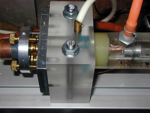
Closeup of one end (without the electrodes)
Here's how the seal is formed between the cooling tube and the plasma tube: RTV silicone rubber is injected through the coolant connection into the space between the tubes. This forms a big O-ring that seals them. Actually, this idea was stolen from one company who makes laser kits (nameless!). They used Araldite epoxy glue instead. I think rubber is nicer; at least you can get it apart again should you need to!
Sealed the other end of the tubes today. Made up a coolant pump using a circulating pump from our central heating boiler.
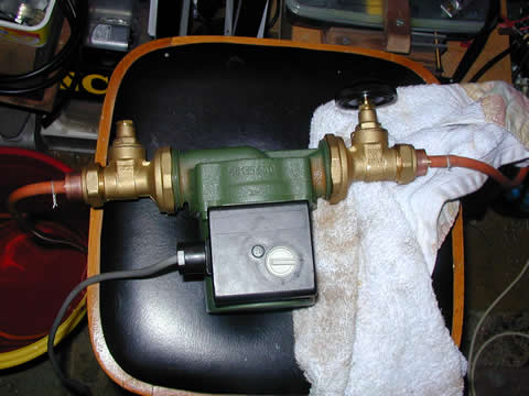
Runs cool! (Dreadful pun intended....)
Here's the overall laser setup:
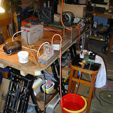
Grey box is the neon sign transformer. Vacuum pump can be seen in background. Red bucket is for cooling water. Cooling water is simply recirculated until the water heats up too much (around 20 mins) at which point the bucket is emptied and refilled.
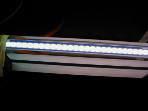
And here's the laser discharge running! Just with air:
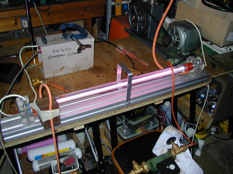
Bands in the tube:
Note: this was with AC. Hopefully a big box of 500 IN5408 diodes will arrive tomorrow and I'll get a rectifier knocked up.
Have also made a plastic spacer to hold the mirrors instead of fixing them directly to the metal of the mirror mount. Will also make two little "caps" to protect the mirrors once they are in place. Pictures eventually.
Tomorrow: to Kilmarnock for laser gas. And maybe, just maybe.......
It works but not as well as I would've expected. I've tried twiddling the flowrate, pressure, current etc but I don't get much improvement from burning thermal fax paper and slightly charred wood.
Can anyone help please? What am I doing wrong?
Removed the RTV rubber seals and simply injected araldite (epoxy resin) to fill the space between the tubes. I'll never get them out again, but at least it doesn't leak!
A little dirt on the rear mirror so gave it a gentle clean. Also some burned on crap on the plastic mirror spacer - possibly vaseline that I put on the O-rings.
Measured the gas flowrate - measure the volume of gas coming out of the exhaust of the vacuum pump and from that you can work the flowrate through the tube. Guess what I had? 38 litres/minute!!!!!!!! It's supposed to be ~2 lpm so some adjustment needed there. But, higher power lasers use a faster gas flow to get more power out so why shouldn't I get more power out with a faster gas flow? Beats me. I tried the little vacuum pump and I can get as slow as 0.6 lpm flow so 2 lpm shouldn't be a problem.
Right, today was pretty interesting. No more power, unfortunately, but something else very interesting...
Anyway, I got annoyed about the adjustment screws on the mirror mounts. The may not joogle from side to side but they are a devil to adjust accurately! So I took the screws out of another mirror mount I had and put them in place of the M6 bolts in the mount. They work a treat, easy to ajust and no joogle. I had to enlarge the holes in the mirror plates because in my hurry to get the holes drilled for the screws, I didn't drill the holes straight. The holes in the plates for the sealing tube wouldn't line up. Enlarged them both to 16mm and that sorted it. I left the rear mount as it was since I only really have to adjust one of them.
Here's a couple of pics of the setup - the new mirror screws:
And the whole front head - note the yellowish araldite seal. It works beautifully!
(Oh, forgot to say that the diodes did arrive and I soldered 30 of them together and put them into a tube. That would be rated at 30kV DC, which is ample margin of error for a 10kV rms AC transformer.)
Another cute note: I tried looking at the discharge from the end of the tube through a little spectrometer (with the mirrors removed, obviously!!). When there's maybe 10 Torr of laser mix in the tube, the spectrum consists of lots of rather broad lines. Consistent with a discharge of a molecular gas such as CO2. When I pinch the gas inlet off, and let it pump down as far as it'll go, some bright sharp lines slowly appear, presumably from air leaking into the tube. Now, you'll probably ask "well, air consists of N2 and O2 which are molecular gases so why aren't their lines broad as well?". Darn it, I hoped you wouldn't ask that....I don't know. Someday I'll go and look up the textbook. 3 years of university and I can't answer that....
Anyhow, on to the interesting stuff. I wondered if it would lase any better at a lower temperature. So, got a couple bags of ice and chucked that into the bucket of cooling water (incidentally, the circulating pump doesn't work any more. It pumps fine without the small hose connections on it, but it doesn't when they are connected. I'm using another 6 volt pump). Managed to get the tube down to about 4 centigrade (before it was at 20 centigrade).
Held up a bit of fax paper about 10cm from the OC and turned it on. A very feeble burn mark. Much worse than at the higher temperature. I tried adjusting the OC but that was the best. Then, completely by accident, I move the piece of paper out of the beam when it was still on. I looked at it and saw a series of small dots! Of course, the NST might be rectified but it isn't smoothed therefore the output of the laser will be pulsed at 50Hz. Very nice - but on closer inspection there wasn't just a row of single dots, there appeared to be a row of triplets of dots!! (Before you ask, yes there's pictures, I have them on a separate page, link later).
I held a piece of fax paper futher away from the OC (~50cm). Guess what? Not one burn mark, but three!!!
I then set up a piece of temperature sensitive LCD (from a toy catalog, I think; press your hand on it and it changes colour with the heat) panel about 1m from the OC. Turned it on and - well, have a look at this page; it contains all the pretty pictures:
Beam Profile Pictures - 26 August 2004
So, all that twiddling is very nice, but it still doesn't get me any more power. At least I've seen higher order mode patterns, which is really something. Considering I can't get them back again, it was pretty lucky to get them!
So far, here's the summary of critical stuff:
1) Current does have an effect on the output. If it's too high, it won't lase, likewise if it's too low. I find that an input of 150VAC to the 10kV NST works best (as measured from the variac)
2) Pressure has some effect, but not that much.
3) Temperature seems to have no measureable effect. I know it probably does, only I can't detect it with just burning fax paper!
I also re-calculated the beam sizes at the OC and full reflector to check them . Both are around 6mm dia (that's to 1/(e^2) intensity) so the 8mm hole in the plastic spacers should pass the infrared no problem. Should be no vignetting.
Right, I had another go at the laser last night. I haven't been at it for a while, since Dad & I are building a new shed. It's actually more of an outdoor lab!
I fixed my old mechanical pressure gauge. It probably doesn't read accurately, but the scale will still be proportional so I can still make some guess at gas ratios.
Made up a gas mixing manifold from some parts I got at a farm auction (yes!). They are stainless Nupro needle valves and stainless flange fittings, the best of stuff. The gas system is now roughly this: Three different gases are mixed through three needle valves, the flow of the mixture ifs regulated by another needle valve. The mixture flows through the laser tube and out through the vacuum pump. I also fitted a needle valve to the vacuum pump so I can adjust the flowrate of the gas.
Tried measuring the current through the tube. Guess what? I'm only getting 10mA or so! How on earth do I get 50mA or more through it, like other people are using? I considered using a microwave oven transformer (which will deliver 2000 VAC @ 0.5A) with a ballast, but I decided not to.
Once I had aligned the mirrors, I found that I was getting the ring pattern of the output beam again! And this time, I couldn't get it to go away, no matter how I twidled the mirrors. Anyway, it burned fax paper, so that was OK.
I set up the laser to use the premixed gas. I then bled in a tiny amount of extra CO2 from a MIG welding bottle. A little amount seemed to help the output but not hugely. On a whim, I tried bleeding in air, hoping that the oxygen would't matter and the extra nitrogen would help. But it didn't; it stopped lasing.
I then decided to take off the plastic mirror spacers to drill them about a bit more. But to my horror, I noticed that some of the plastic had been burning due presumable to a discharge jumping to itwhen I was adjusting the mirror mounts. And, even worse, that the output coupler had several small specks of dirt on it!!! One even looked (gulp) burned on. I have emailed LRO and asked what I can clean the mirror with, or if it's even salvageable. So one major lesson folks:
NEVER LET PLASTIC GET IN CONTACT WITH AN ELECTRICAL GAS DISCHARGE!!!
Quite honestly, I'm getting a bit fed up with this whole escapade. I thought I'd no more ado than plug it all together and I could burn holes in firebrick. No such luck. Let's face it, I have no pressing need for a CO2 laser, but if I really, really needed one, I could probably get it working. Time's getting short (I start back at university in a few week's time) and I'm thinking about other things anyway. I'm interesting in trying to make copper-indium-diselenide (CIS) solar panels, so maybe there'll be a new section on that up soon. And we still have the shed to finish. And I want to try making some electroluminescent panels. All in all, there's a hell of a lot of other stuff I'd like to do! So this might be the last post on the CO2 laser, I'm afraid.
| ▲ Homebuilt CO2 lasers |