
| ▲ Vacuum |
The following documents the design and construction of a vacuum system incorporating a diffusion pump and belljar. It was originally intended for doing vacuum metallizing but is applicable to any other experiment where a high vacuum is needed.
What I'll do is simply go through the photos I've taken of the system and describe each one. They are roughly in chronological order!
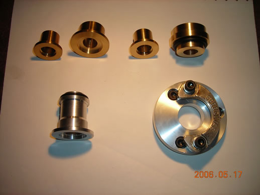
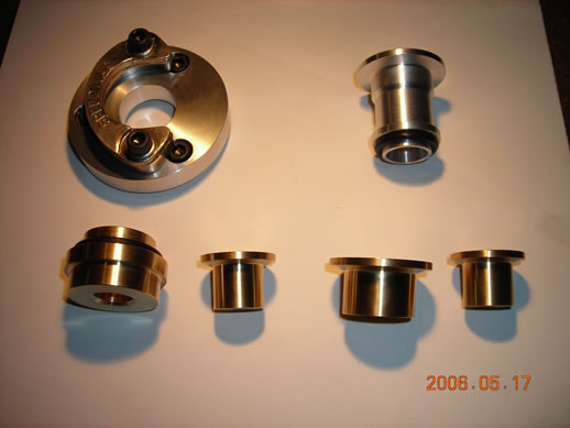
Clockwise from top-left, these fittings are:
It was quite tricky to turn the right sort of taper for the NW fittings (should be 15 degrees) but luckily they don't seem to bother too much!
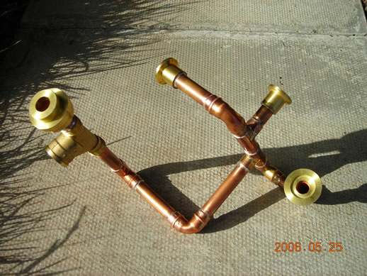
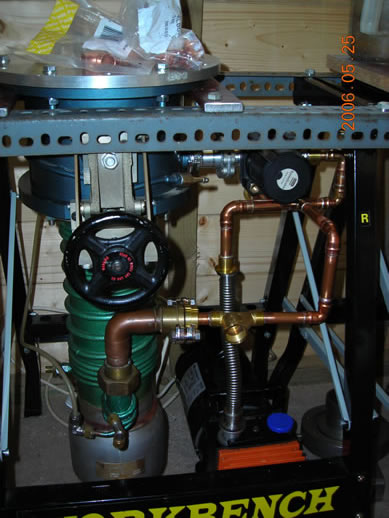
This shows the completed foreline assembly. It was fabircated from 15mm copper plumbing tubing with end-feed soft-solder fittings. The various connections are to the diff pump, roughing pump, Pirani gauge and roughing valve.
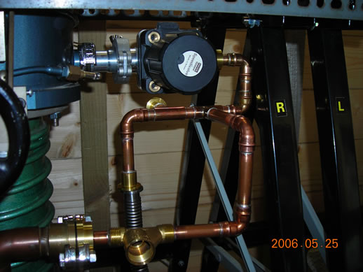
This is a shot of things while I was assembling the foreline. The valve at the top of the picture is the roughing valve. Big green thing at bottom left is the diffusion pump. Big blue thing at top left is the high-vacuum valve.
Here's a better shot of things. The diffusion pump is a 4" throat Genevac type, and was very generously lent to my by the technician at university. I'm much obliged to him for that! I guess it's got a pumping speed of ~120Ls-1. The blue high-vacuum valve is of the Edwards cantilever type and is one of a pair I got out of a skip at university. The roughing pump is down at the bottom-right and is one of a pair I got second hand from the Alcatel service center in Livingston. It's a 2-stage pump and although it's about 20 years old it still works very well. The technician at Alcatel gave it a clean up and got it working - many thanks to him!
The top of the HV valve is covered by a large disc of aluminium (also out of the skip). Notice that the cooling lines haven't yet been connected up in this photo.
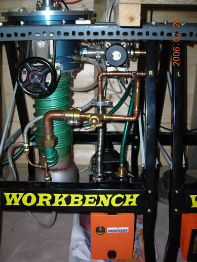
This is a photo of things completed. The cooling lines have been connected and run over the diffusion pump and around the high-vacuum valve. The HV valve also acts as a water-cooled baffle.
Notice the construction of the frame - it's made out of two workbench things from Homebase. They are really excellent and will withstand quite a load. In fact, nearly all the benches in the garage (~6) are made from them! They only cost £12 as well.
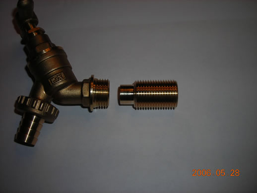
This is one of the three garden taps I used for connecting the cooling water lines via the shed wall. The thread wasn't long enough on it so I had to turn up & thread an extension to solder into it.
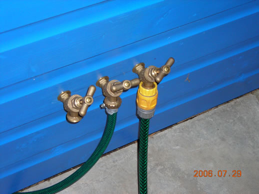
The three taps on the outside of the shed. From left to right - vacuum pump exhaust, water outlet, water inlet. The inlet uses a Hozelock connector.
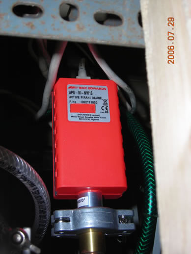
An Edwards APG (Active Pirani Gauge). This gauge measures the foreline pressure and since it's an active gauge, it only needs a power supply to operate. I bought this for £120 from Island Scientific.
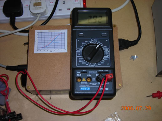
The controller I made up for the Pirani gauge. The graph taped to the box shows the response of the output of the gauge.
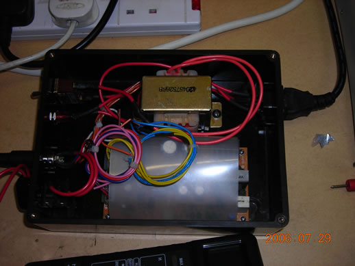
Inside the box (which was also out the skip, BTW). It's basically just a 22V DC power supply. The transformer and circuit board were from a photocopier I got out the skip.
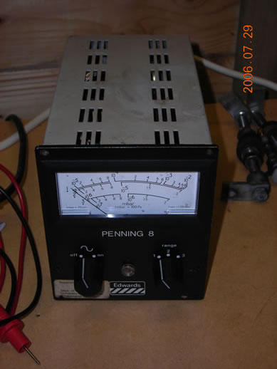
The Edwards Penning 8 gauge controller I use for measuring the high-vacuum pressure. This one's on kinda permanent loan from the Physics department at university! I should ask them about that sometime ;-)
The gauge head. Basic idea - the current flowing between two electrodes is dependent on the pressure of the gas between them. There are magnets around the electrodes to increase the path length of the electrons and hence the conductivity. It's also called a cold-cathode ionisation gauge.
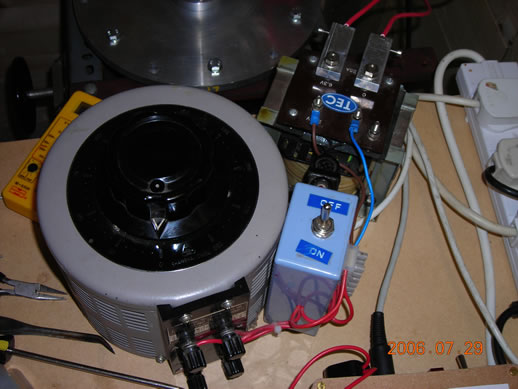
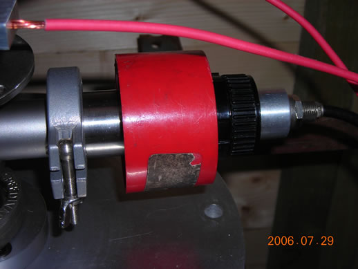
This is the power supply I use to run the evaporation filaments. It consists of a Variac running a 6V, 25A thyratron filament transformer. The 150W output is enough to run quite a few types of filament.
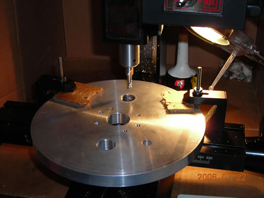
Machining the holes in the baseplate to accept the two power feedthroughs (20mm OD) and a 15mm blanking plug for a stupid hole I made by mistake!
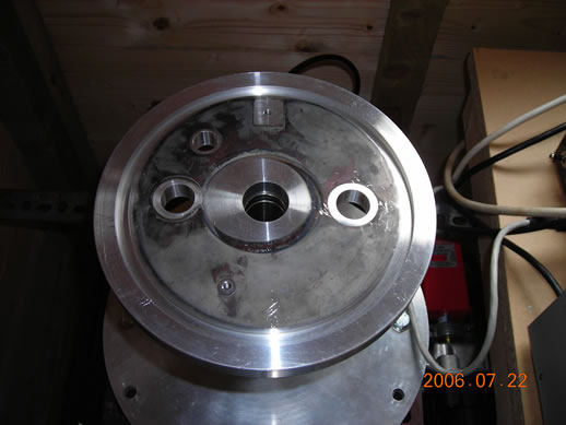
The baseplate mounted on top of the vacuum system.
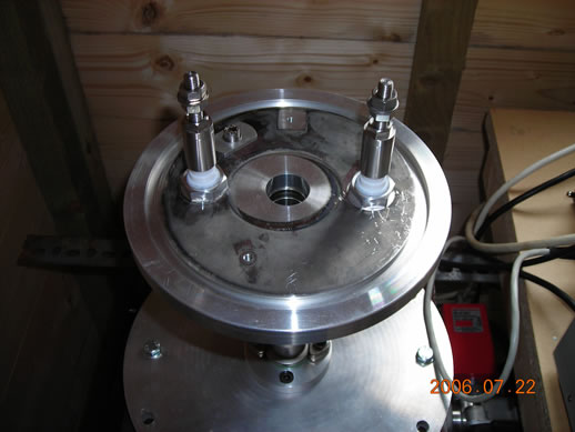
Feedthroughs and blanking plug fitted.
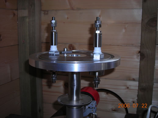
Another view.
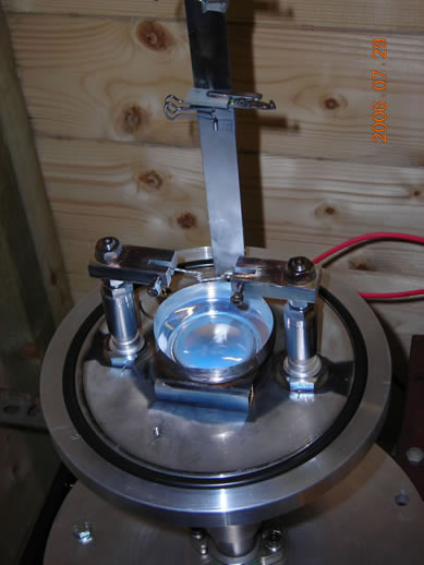
This shows the filament connections as well as the "substrate holder" - a bracket with some Crocodile clips! There is a cup fashioned from the bottom of a Coke can underneath the filament to catch any metal that falls off. The cup is supported to clear the pumping port underneath.
The 15mm blanking plug to block of the silly hole I made by mistake.
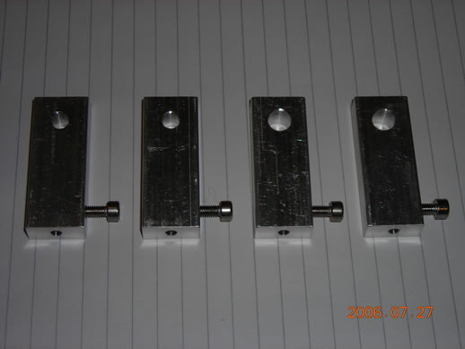
The four electrical connections which go on the outside of the feedthroughs and on the power transformer. There's a hole for a wire and a setscrew to hold it.
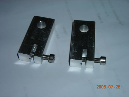
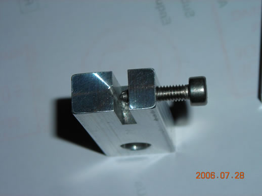
These two shots show the holders for the filament. The slot was produced by first drilling a 2mm hole into the end of the aluminium bar and then running a slitting saw down the bar to cut away half the hole and leave a little groove for the filament wire to locate in. It's a very secure method of holding the filament.
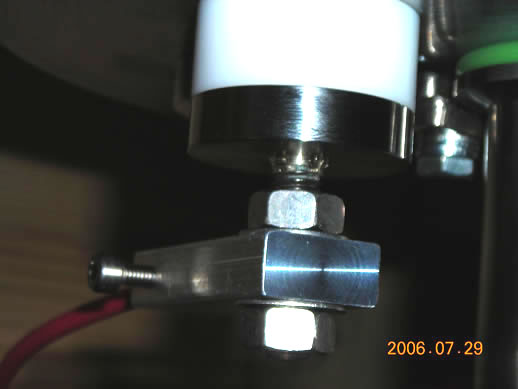
This just shows the power wire connected to one of the feedthroughs on the outside of the vacuum chamber.
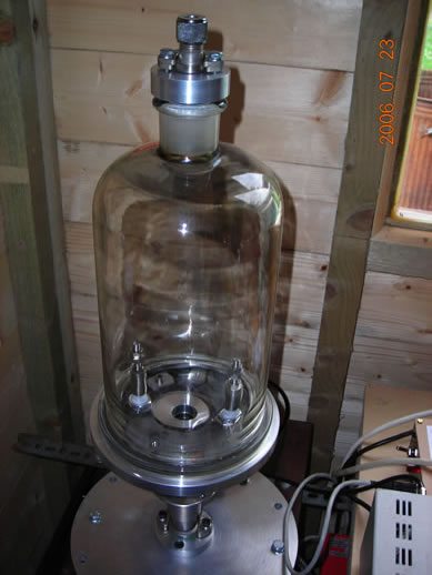
This is the glass belljar. The thing on the top is an air-admit valve which seals against the neck of the jar by the force of the vacuum.
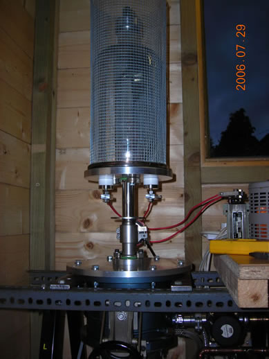
Another shot of the belljar and protective screen (which I doubt would do any good if the belljar actually DID implode, but it's better than nothing!). This was after a few evaporations, hence it's shiny.
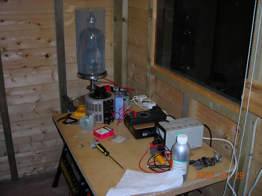
This is just a shot of the overall system in the shed!
Modifications will probably be made to the system as time progresses (viewing window, HV feedthrough, metal shields, etc...).
As it stands (29/07/06), I can get a vacuum 1E-5mBar in the belljar after about 90 minutes of pumping. Not bad, considering the NW25 pumping tube (about 1" dia) is probably choking the diffusion pump! With the Penning gauge stuck right on top of the HV valve, I managed to get 1.5E-6mBar after 3 hours pumping. The big thing that takes a while to pump is water vapour - once I find a nice neat way of either making/getting hold of some liquid nitrogen, I'll maybe incorporate a trap.
I've added a couple of things to the belljar, namely the HV feedthrough, a substrate holder, a viewing window and a shield on the inside of the belljar. Photos below.
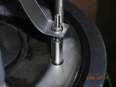
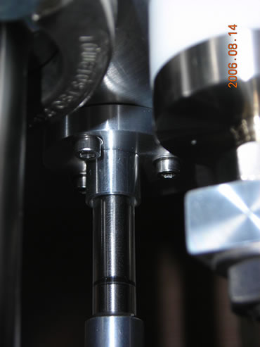
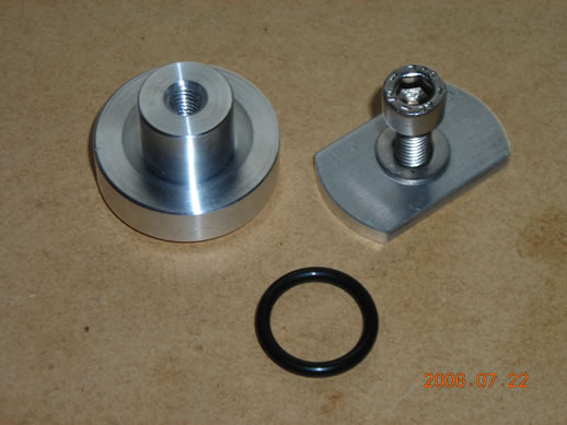
These are a couple of shots of the HV feedthrough on the baseplate of the belljar.
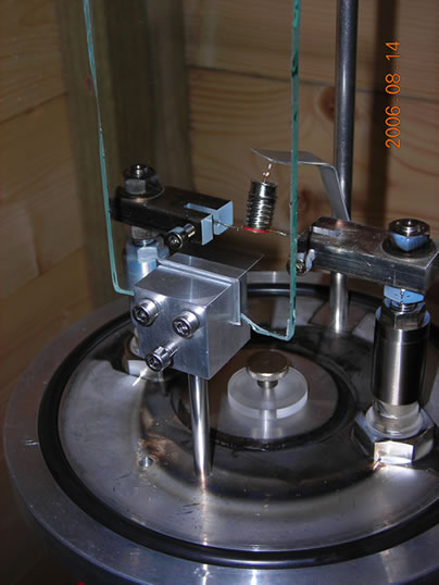
This shows a glass viewing window and holder I knocked up. The idea is that the evaporated metal coats the piece of glass instead of the belljar. The glass can be removed and cleaned.
The substrate holder. It accepts a 96mm diameter substrate or mask.
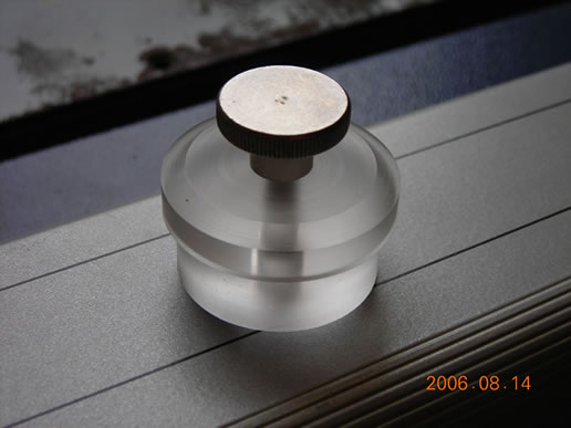
An extremely useful thing! A little plastic plug for the baseplate so stuff doesn't fall down the pumping port when I'm working on the belljar.

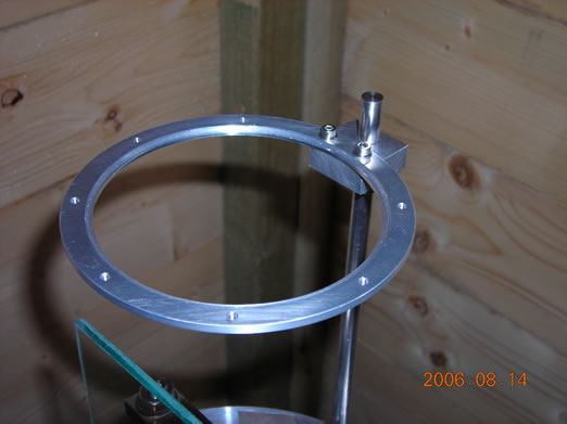
Metal screen on the inside of the belljar, with a hole cut for the viewing window.
Couple of things I plan to make next. First a little shield which goes really close to the filament and prevents anything on the baseplate getting coated (namely the HV feedthrough). Also, if I mounted a little mirror higher up on the belljar, I could look through the viewing window at the mirror and be able to see the filament that way, even though direct line of sight was blocked by the shield. That way I wouldn't have to clean anything when I was done coating!
| ▲ Vacuum |