| ▲ Vacuum |
After I'd built my first Panaplex display, I came across a beautiful example of a miniature commercial display which was used in desktop calculators. It's the Elfin Rodan MG-17, with a "D" or "G" suffix depending on the anode construction. The MG-17D has a wire mesh anode in front of the cathodes, like the vast majority of other Nixie and Panaplex displays. This is alright, but it is visible and tends to obscure the cathodes. However, the MG-17G has a sheet metal anode with apertures cut out which correspond to each cathode segment. The glow around the cathode is then confined to the opening in the plate. This construction looks much nicer (and is a bit easier to make) so I decided to go with it.
The three pages linked below have some great photos of both devices in operation. These are backup copies hosted on this site, with links to the original page source. (If you need to see the Japanese characters correctly, use the Shift_JIS encoding.)
If you look closely at the MG-17G, you should be able to make out the construction. The cathodes are bent pieces of wire in the shape of staples, held in a ceramic or glass backplate. The lead-in wires are welded to the cathode wires behind the backplate and the anode is riveted to the front of the backplate. This is the structure I'm going to try and replicate.
A CAD drawing of the display is available here as a Rhino 3D file (version 4 of Rhino) or here as a PDF (scale 8:1).
I decided to make the backplate from glass by melting glass powder in a suitable mould. Making small holes in the glass to accept the cathode wires was difficult, but I finally realised that propelling-pencil leads, which are a graphite/clay mixture, could be used to leave a hole in the glass after it melts. The pencil lead can be pushed out of the glass later to leave a suitable hole.
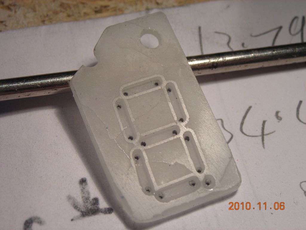
The backplate has seven rectangular cavities for each of the segments, a single cylindrical cavity for the decimal point, and two 3mm holes for the mounting screws which hold the anode plate on the front. The final overall thickness was around 2 to 2.5mm. The cavities are 1mm deep and are designed for cathodes made using 0.6mm wire, so the wire stays below the front surface of the backplate. Holes (0.7mm diameter) are formed in the cavities by the pencil leads, allowing the cathode wires to be passed through the backplate. Rather than using a "square" display, I made one with a 4° tilt to incrcease readability.
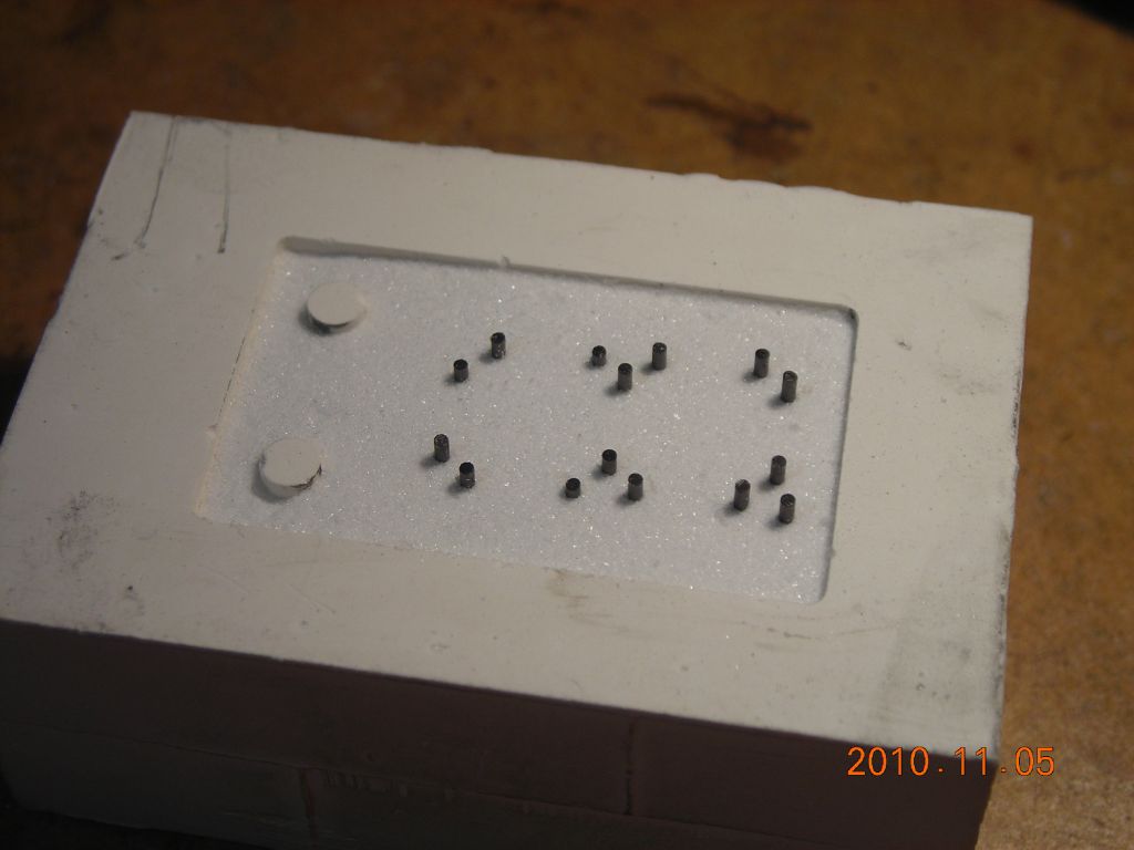
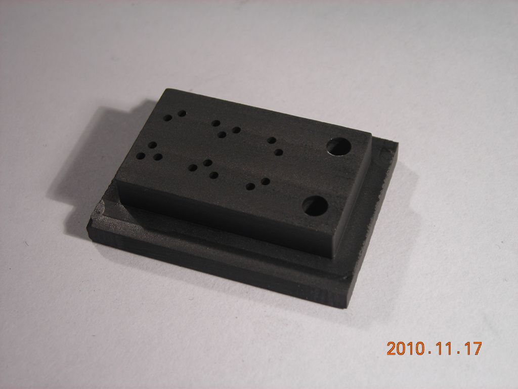
A master model for the final plaster mould, which is used to cast the glass, was milled out from some PVC sheet. Holes were drilled in the model to accept 0.7mm pencil leads. With the leads in place, a mould was made with silcone RTV rubber. This was then used to make the plaster moulds. Pencil leads are cut to length and inserted into the holes left in the rubber mould. Plaster is mixed up, degassed and poured into the rubber mould where it is degassed again to ensure it flows into all the cavities and holes.
I should make some comments about the plaster. I initially used standard plaster of Paris (Prestia casting plaster from Tiranti). This worked pretty well, but did have a tendency to crack up while being fired in the kiln. Although I did managed to get an acceptable backplate out a plaster of Paris mould, which I then used to make the Panaplex display shown here, I tried one mould made from proper glass casting plaster (from Warm Glass) and this performed much better without any cracking. In either case, the moulds were dried for a couple of days on the radiator before being fired in the kiln, to ensure there was no water left in the plaster.
Glass powder cannot just be poured into the mould and allowed to melt, since it tends to "draw" together as it melts. To prevent this, I made a graphite "plunger" which sits on top of the glass powder and keeps it in contact with the mould. The first plungers were made from quite a coarse-grained graphite (mainly because I have a large chunk of the stuff) and only survived a single firing in the kiln, oxidising rapidly. I later bought a chunk of fine-grained graphite block from Olmec which proved to be much more successful.
Unless the graphite plunger is constrained to move in a vertical direction only, it often tilts and the resulting glass piece is severely tapered. To prevent this, I made a little press which sits inside the kiln and ensures vertical movement of the plunger. It's all made from stainless steel, and the guide arrangement is simply a rod and disc with the rod sliding in two holes in a piece of box section tube.
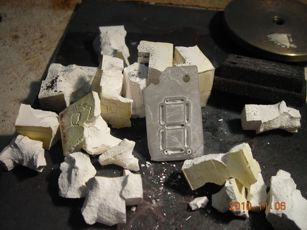
So, the mould is filled with glass powder (Bullseye transparent powder frit from Creative Glass Guild), the plunger is placed on top to compact the powder, and the whole assembly is placed into the press and into the kiln. I found that firing at 750°C for ½hr seemed to give good results. The kiln is allowed to cool naturally to anneal the glass. Afterwards, the mould can easily be broken up and the glass removed and finished with some grinding/sanding of the edges.
The photos below show all the stages in making the backplate, from making the model for the mould right through to the final glass backplate. The two photos which show the mould being fired with just a weight on top in the enamelling kiln were the very first attempt. After that, I stuck to the proper kiln (a Paragon XPRESS-Q-11A) which has proper digital temperature control. I went through nearly ten attempts before finally getting a decent backplate! I found I had to clean up the holes in the backplate using a 3mm diamond drill for the two large holes and a 0.6mm carbide PCB drill for the cathode wire holes.
 Mould master model |
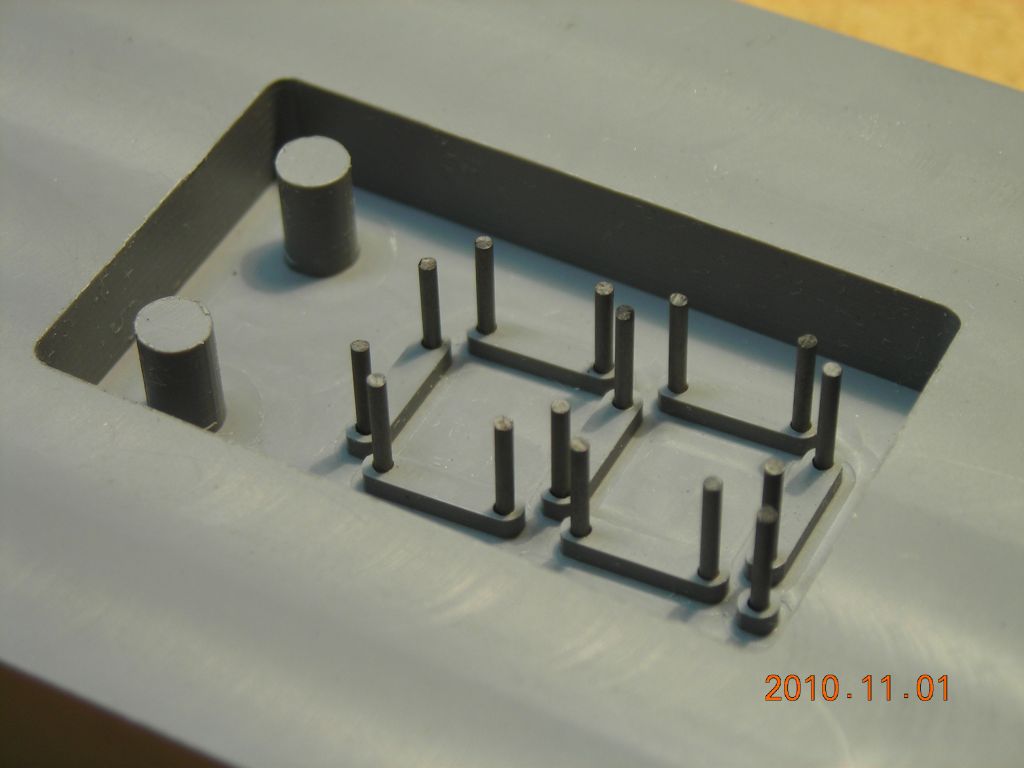 Pencil leads inserted |
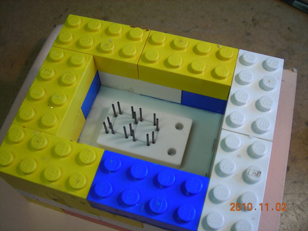
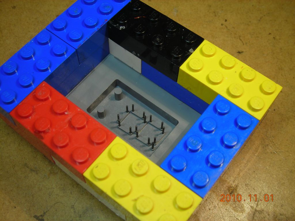 Lego frame built up to hold rubber |
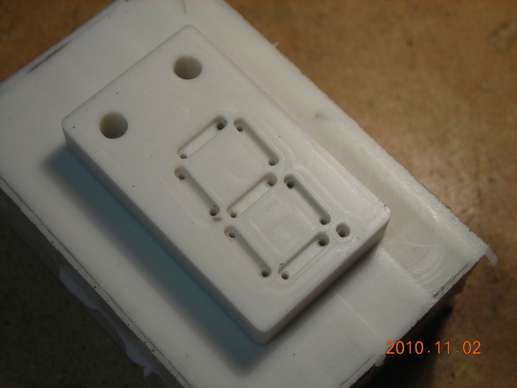 Silicone RTV rubber mould with pencil leads removed. This is what the final backplate will look like. |
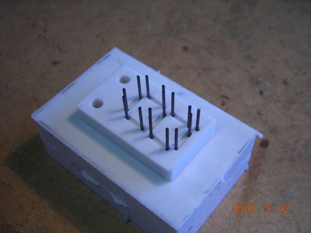 Pencil leads cut and placed in holes in rubber |
 Another frame built around rubber mould |
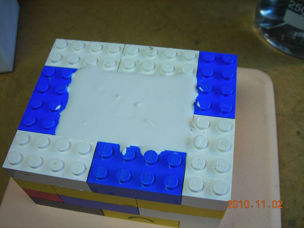 Plaster mixed, degassed and poured into frame (also degassed while in frame) |
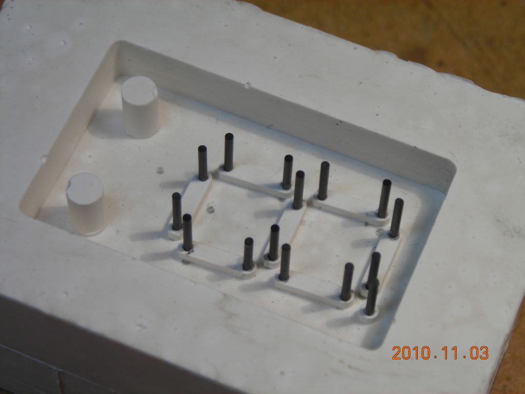 Resulting plaster mould, with pencil leads embedded in the plaster |
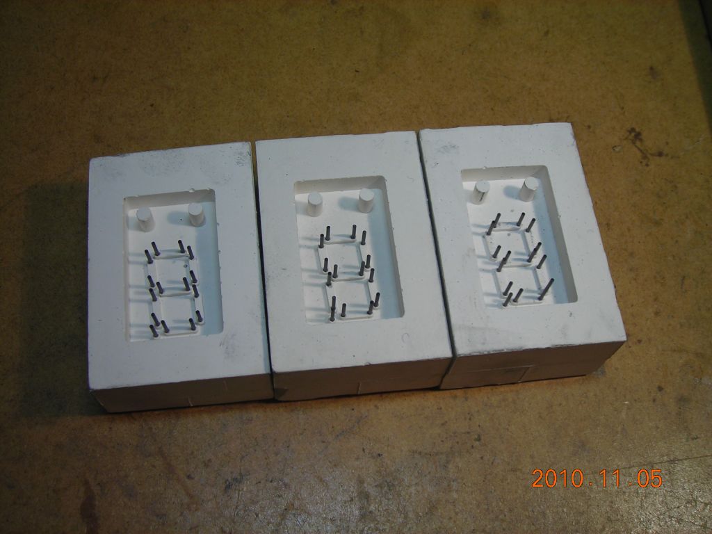 Several moulds |
 First graphite "plunger" |
 Top view |
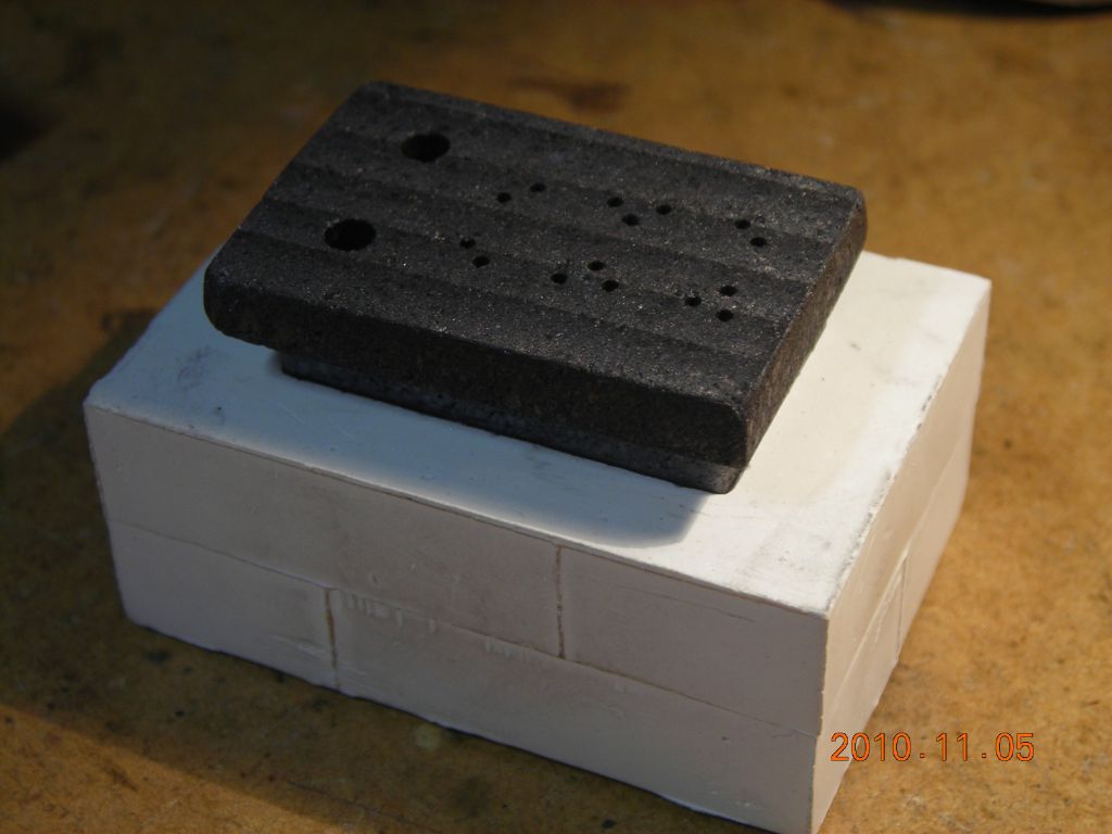
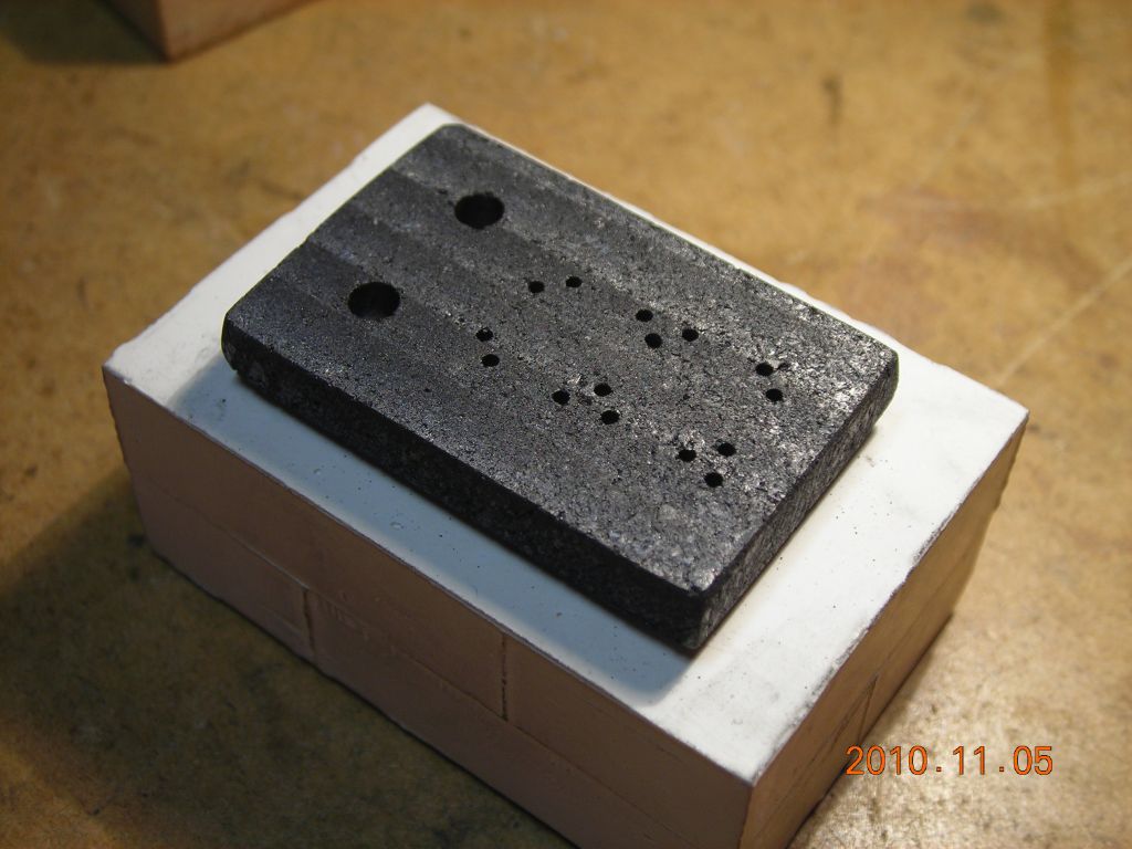 Showing how it fits the plaster mould |
 Glass powder poured into mold and compacted |
 Graphite plunger placed on top |
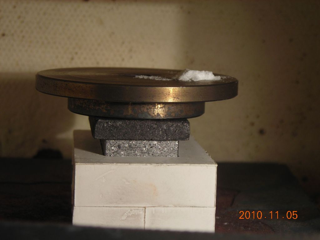 Weight placed on top and whole lot put into small enamelling kiln |
 End result after about 1 hour at ~800°C |
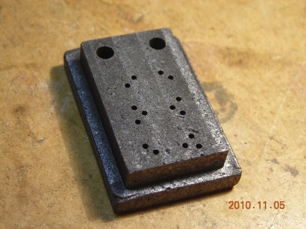
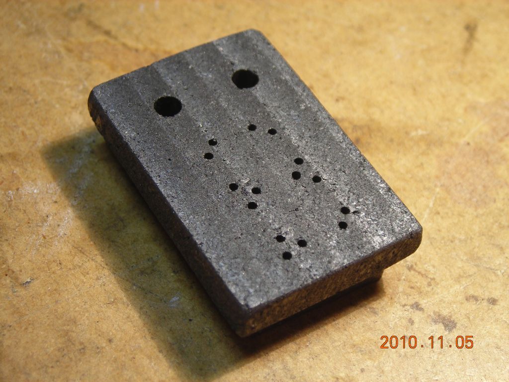
 The first (of many!) backplates I made |
 A new graphite plunger made from much finer-grained graphite |
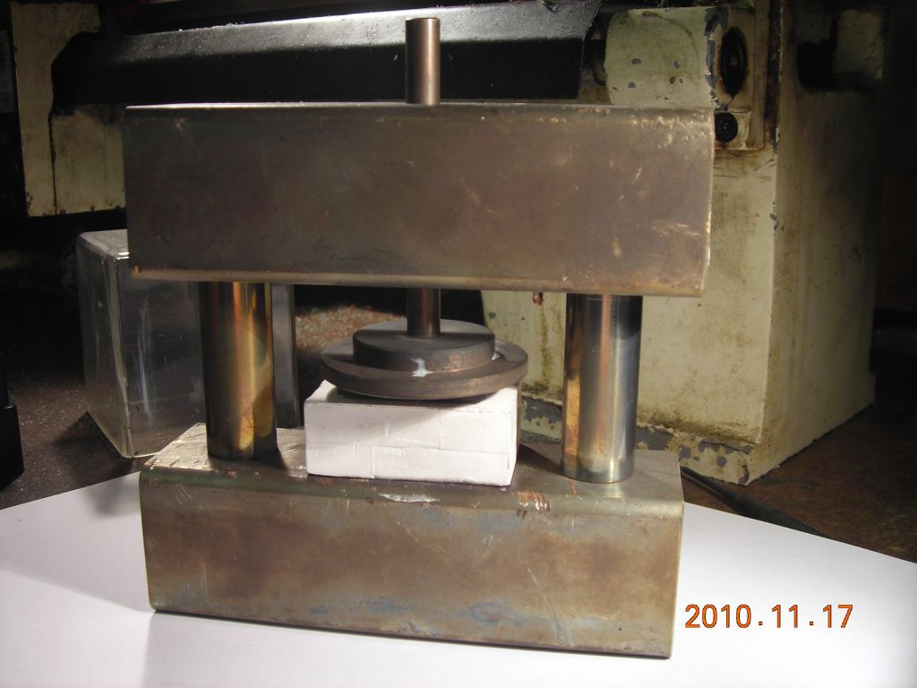 Vertical press assembly for the kiln to prevent graphite plunger from tilting (all stainless) |
The anode plate is quite simple. It is machined from 0.5mm-thick aluminium sheet. Although the aperture sizes and spacings were taken from the original drawing, and did not account for shrinkage of the glass backplate, the overlap/misalignment isn't large enough to be a concern.
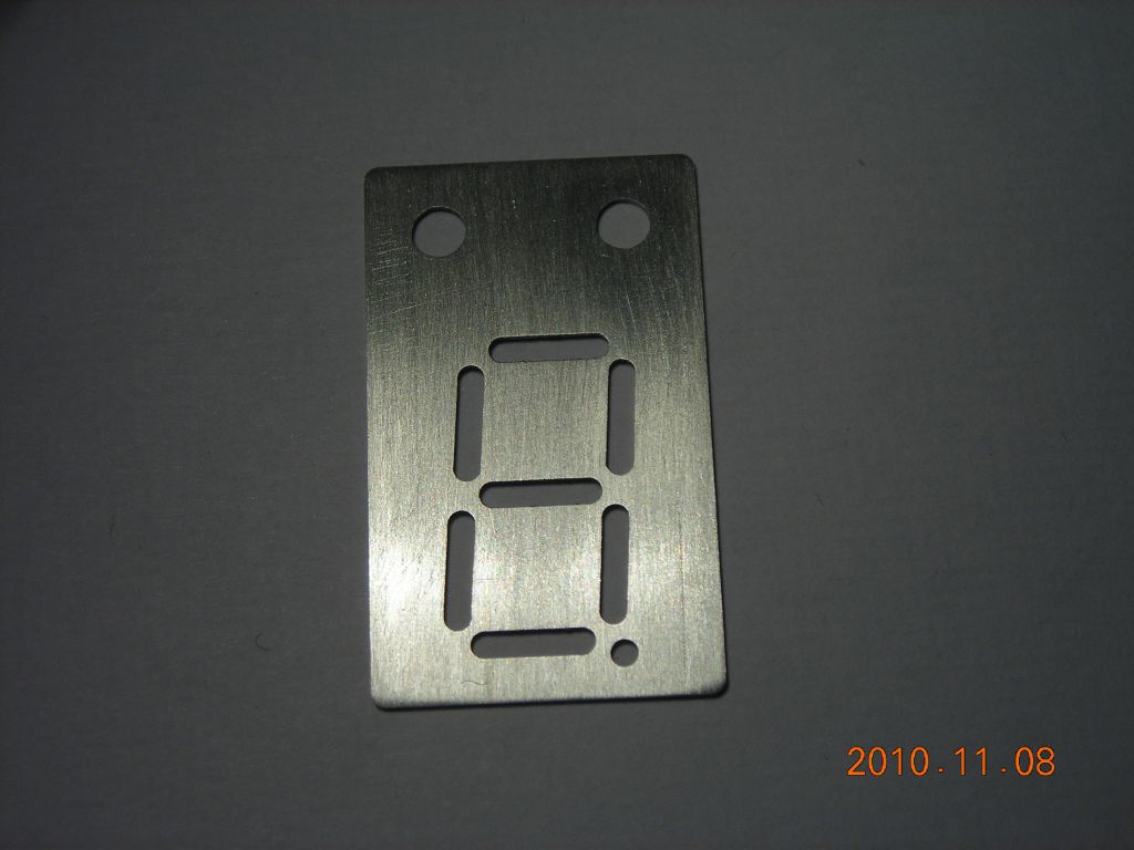 Anode machined from 0.5mm aluminium sheet |
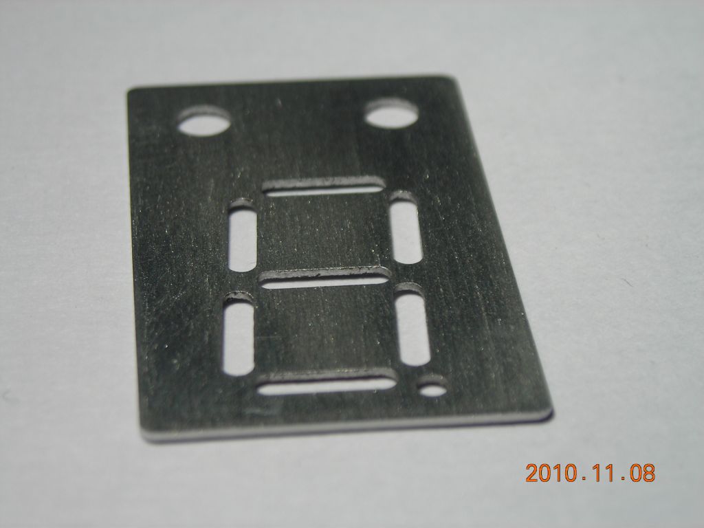 Another view |
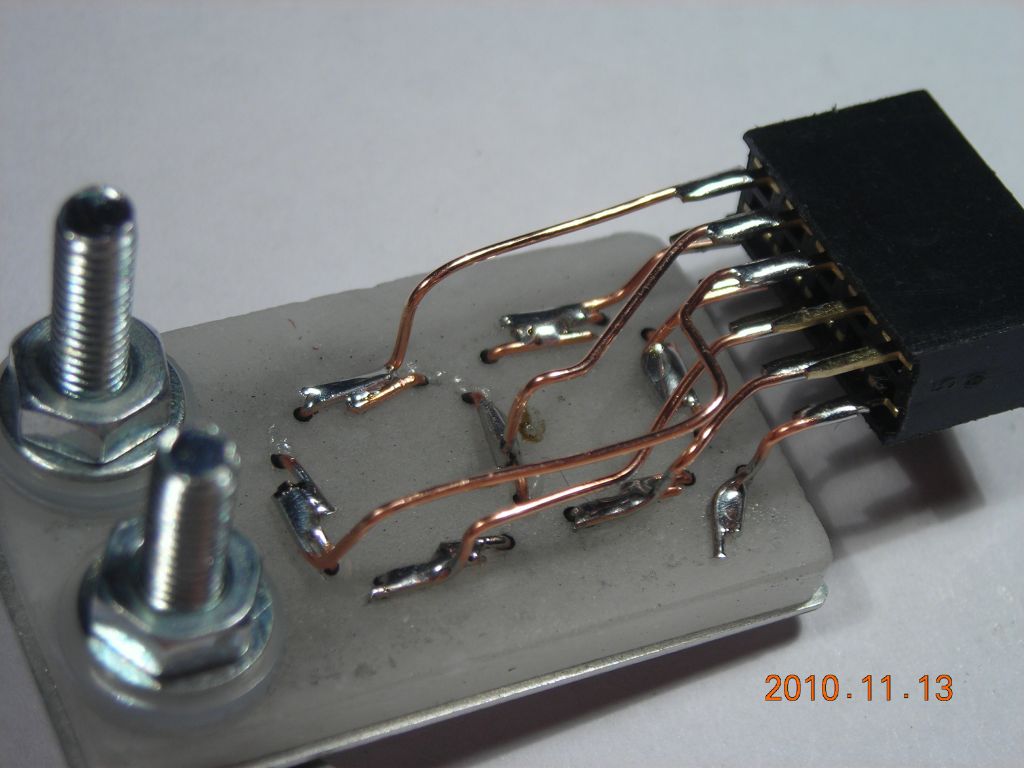
The first step is to insert the cathode wires into the backplate. I used 0.6mm diameter bare copper wire (from the wires in an Ethernet cable) which isn't the best because of sputtering, but it was soft and easy to bend. Each of the segments is formed from a little staple of wire with the legs bent over at the rear of the backplate. The decimal point is formed from a single piece of wire. The anode is then screwed to the front of the backplate and aligned so the cathode wires appear centered in the apertures in the anode. Finally, I soldered on a 2x5 pin header to make connection with the various cathodes. It's a bit tricky squeezing the wires in without touching, but it's possible. A single solder tag makes connection to the anode.
The display is mounted in the same vacuum chamber used for the previous display and the anode wire is clipped to the bolt feedthrough. I used a set of eight switches to quickly switch off/on the various segments. Note that, in proper Panaplex displays, each cathode should have its own current-limiting resistor to share the current equally between cathodes. However, in this display, I found I could simply connect several cathodes together and they would all light up, without any problems of the discharge jumping to one cathode.
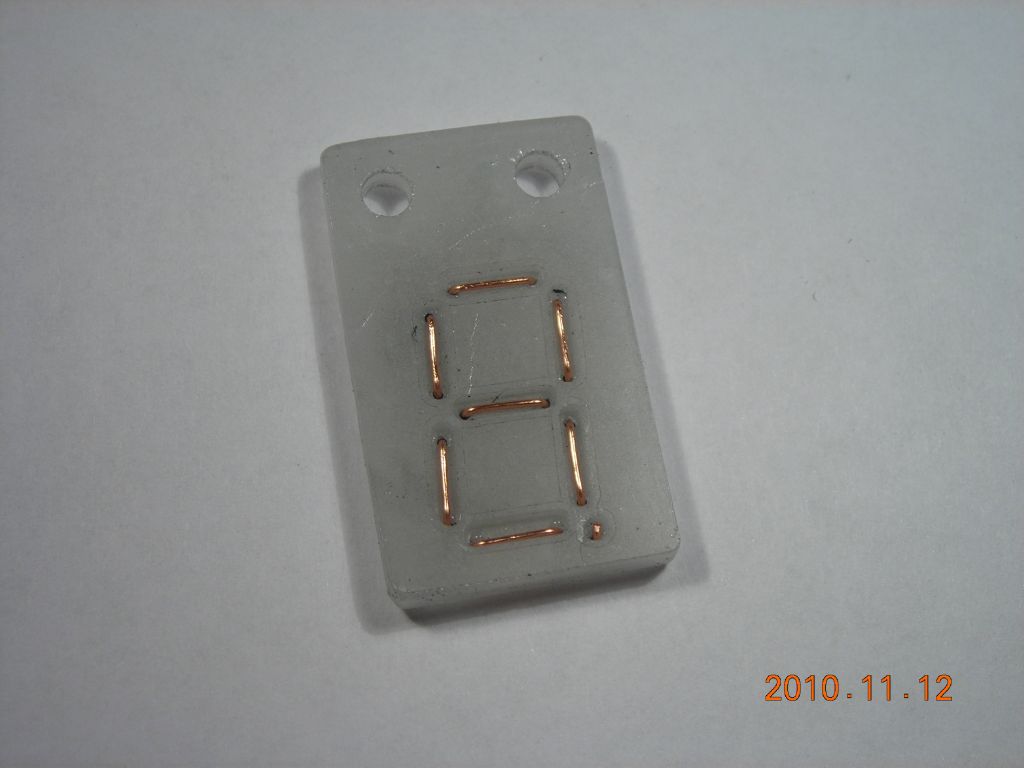 Front view showing cathode wires in place. The decimal point is a single piece of wire. |
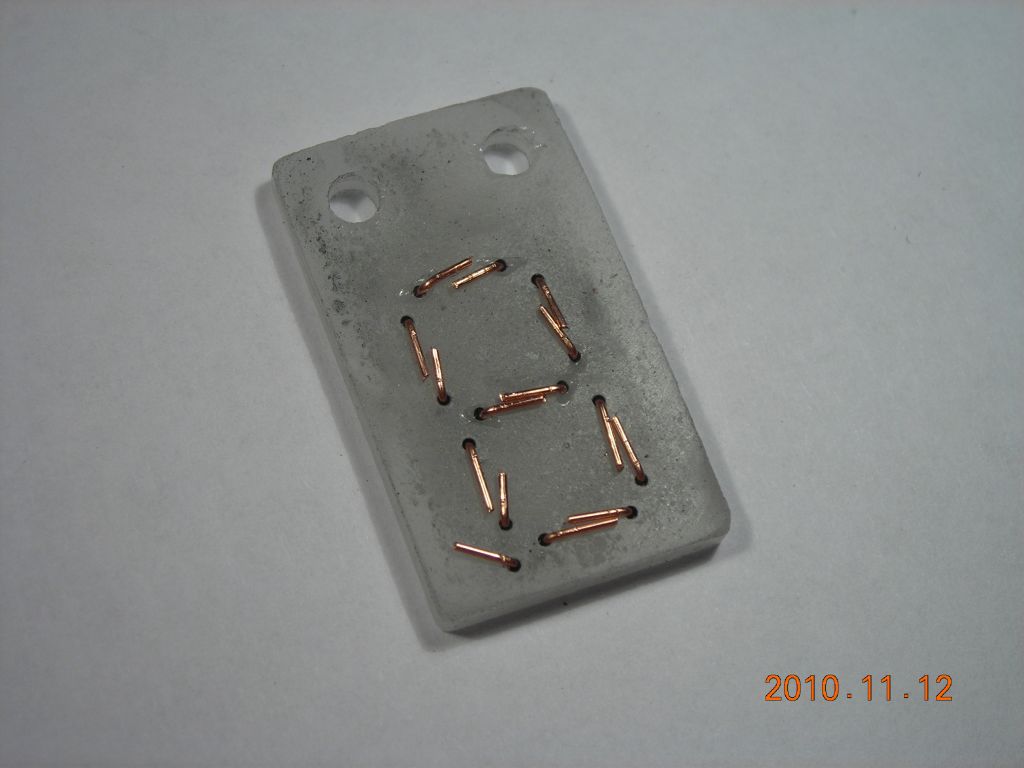 Rear view with cathode wires bent over |
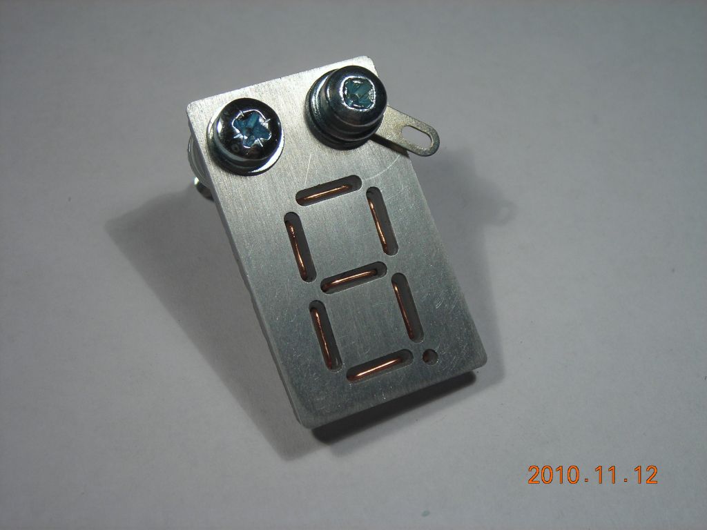 Anode screwed to front of backplate. Nylon washers are used behind to protect the glass. |
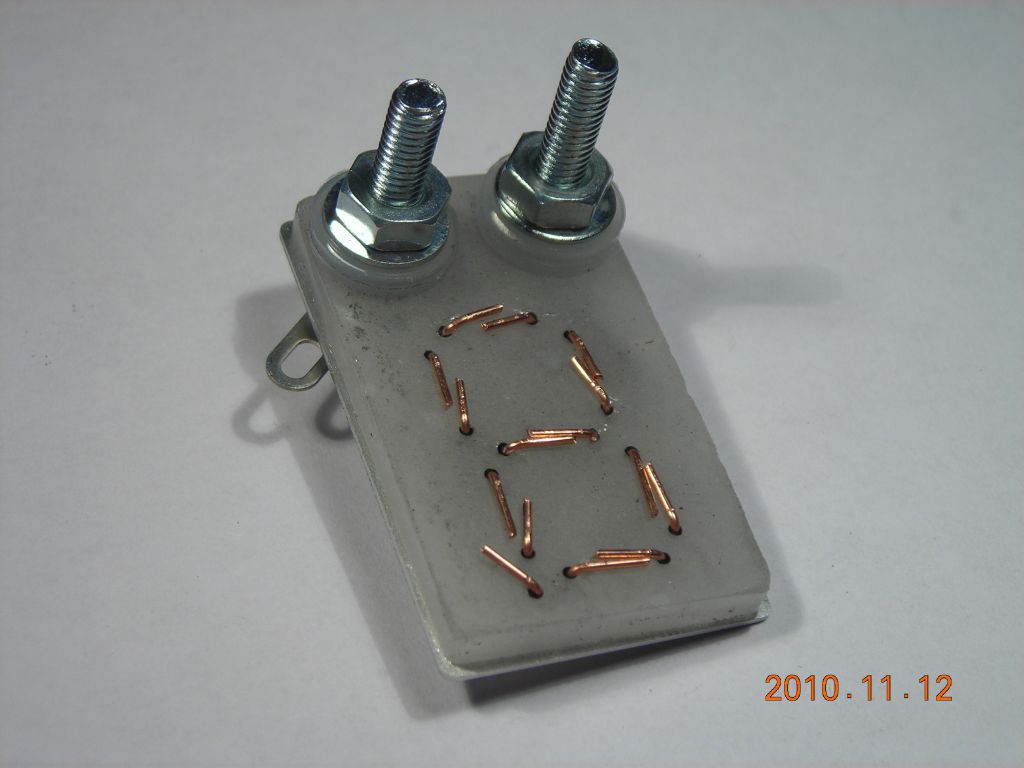 Rear view showing nuts and washers |
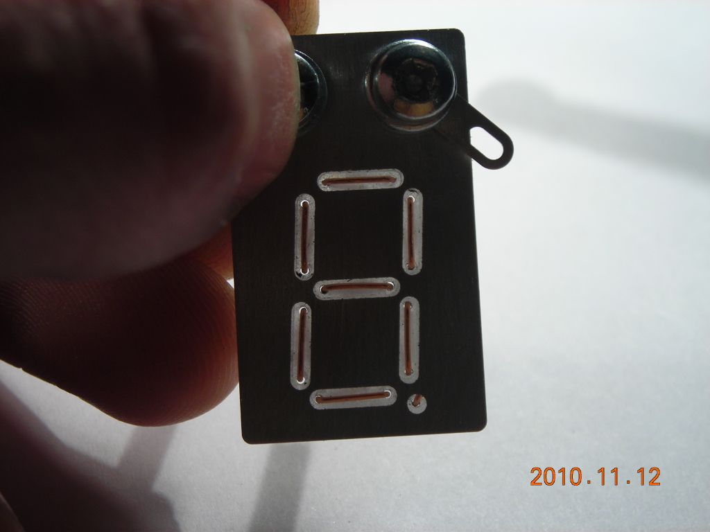 Light shining through the backplate. Note how the cathodes are centered in the corresponding anode apertures. Light shining through the backplate. Note how the cathodes are centered in the corresponding anode apertures. |
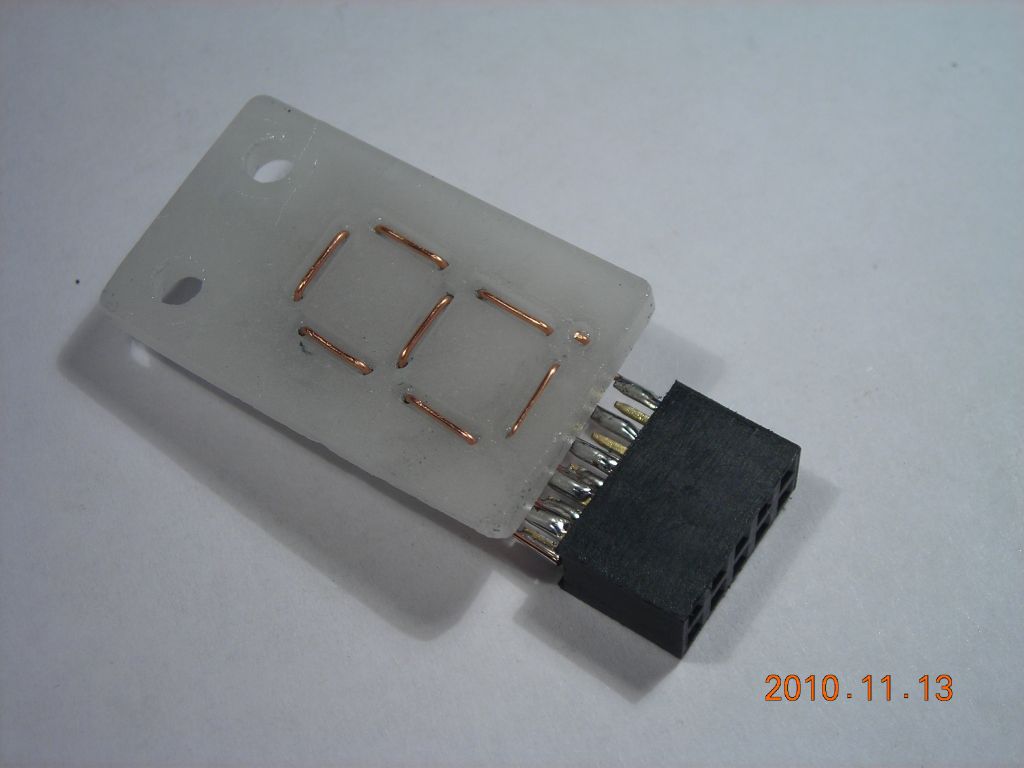 A 2x5 pin header connected to the cathodes (anode removed for convenience) |
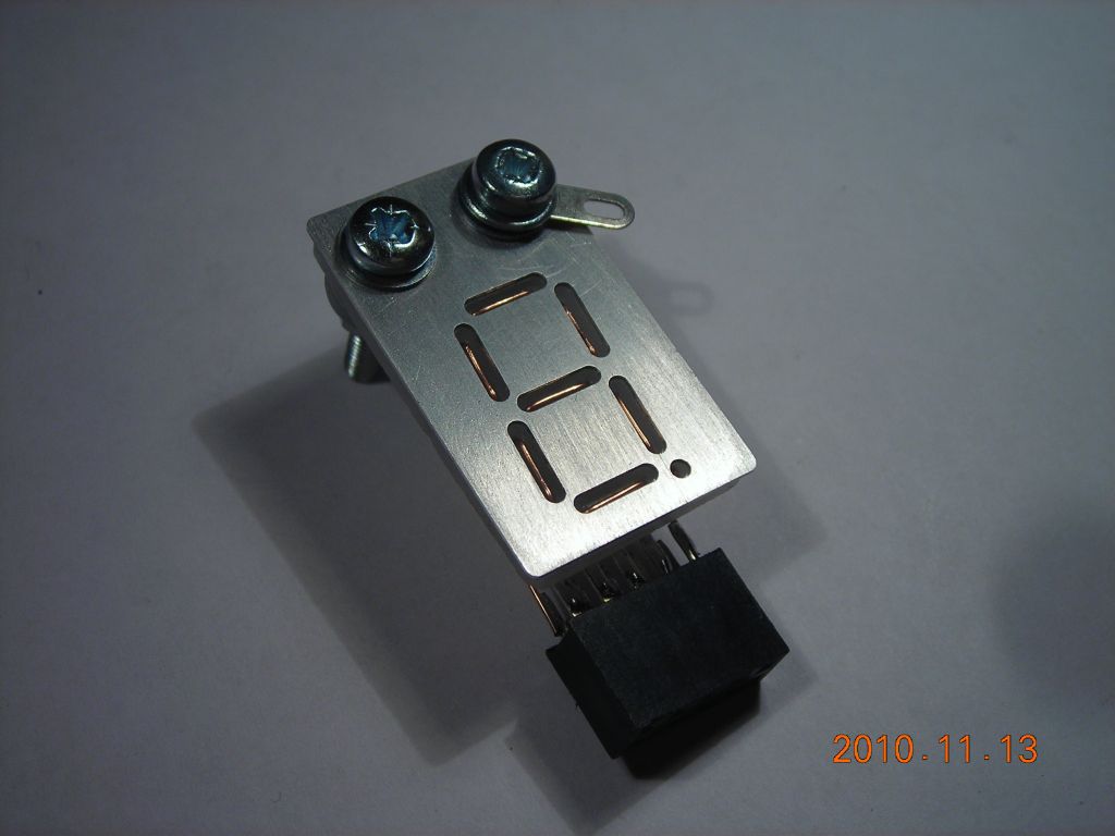 Anode mounted again |
 Wiring connections to cathodes. Care must be taken not to short wires. |
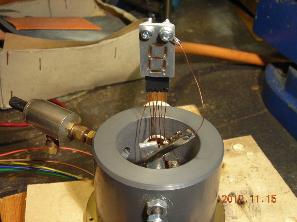 Display mounted in the little jamjar vacuum chamber used for the previous Panaplex display Display mounted in the little jamjar vacuum chamber used for the previous Panaplex display |
 Eight switches used to control which cathodes are lit Eight switches used to control which cathodes are lit |
It seems to run happily in air, although argon does make the discharge more purple. I used my 30kV flyback supply again, but obviously it doesn't deliver that when the display is running. Depending on how many segments are lit, the voltage drop across the display is around 400-600V. This is obviously much higher than if neon were used, but air or argon is far less conductive than neon. I had to make sure I never turned all of the segments off, because then the voltage across the switches would rise to 30kV (the open-circuit voltage of the power supply) and they would arc.
If the voltage or current is turned up too high (no figures here, just qualitative) the discharge jumps to the connecting wires behind the backplate. The display then dims, since the discharge is being split between the front and rear. The current must be limited to prevent this. Alternatively, as I've seen in some Nixie tubes, the lead-in wires can be coated with an insulating ceramic paint/glaze/covering which is vacuum-compatible but doesn't outgas and prevents a discharge forming.
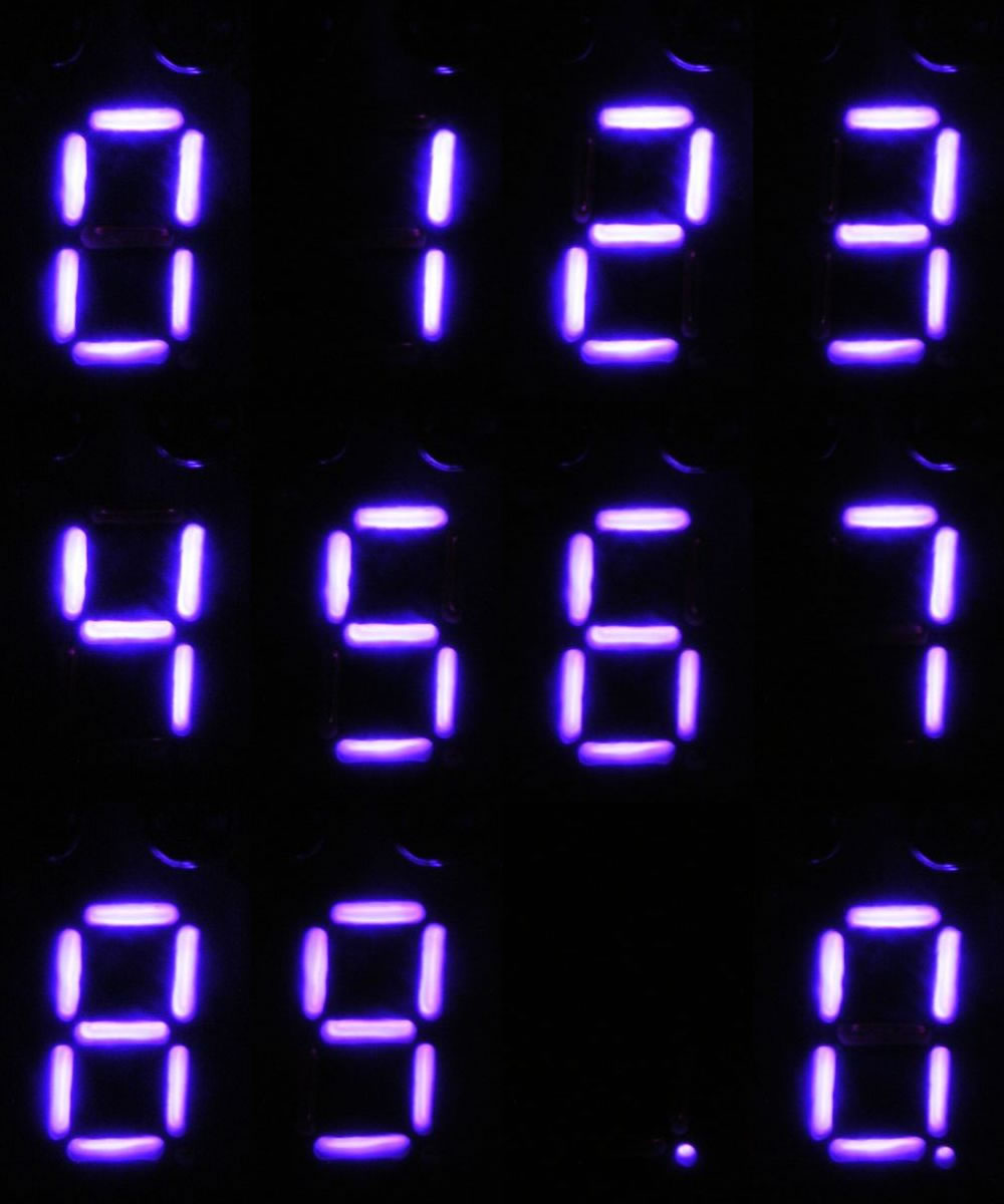 Montage showing the numerals and decimal point |
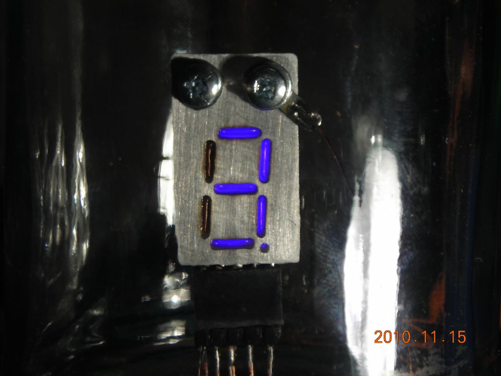 Brighter view of "3.". Glow is confined nicely to the anode apertures. Brighter view of "3.". Glow is confined nicely to the anode apertures. |
Finally, here's a video showing the digits 0-9 and the decimal point being switched-in manually. Although the voltage is rather high for a discharge display, it would still be possible to switch the cathodes with transistors, since both MOSFETs and IGBTs are available in voltages up to above 1kV.
It's still my intention to try and make a sealed-off Panaplex display (possibly contained inside a triode valve envelope, or a test tube) which could be used in a clock, perhaps even a four-digit multiplexed display with separate anodes. I have never seen an argon-filled Panaplex display - all of them are filled with neon which, although it does look great, is a bit common! Yes, argon is a lot dimmer than neon, but I think the purple colour is quite unique. At least I know it is possible to make the Panaplex part of things - I still need to sort out envelopes, feedthroughs, glass joining/seal-offs etc. which will probably be a long process. Watch this space....
| ▲ Vacuum |