| ▲ Workshop |
A glass lathe is something I've always wanted. I've tried freehand glassworking, but I never had the patience to learn doing it properly. With a glass lathe, joining tubing, making seals etc., become dead easy and a whole range of possibilities present themselves. My primary desire is to make small vacuum tubes. Unfortunately, glass lathes are nearly always made rather large, and there is nothing available on the scale I'm working on (around 1" diameter). So I had to make one!
A glass lathe is very similar to a metalworking lathe, except that it has two spindles which are synchronised and rotate together. One spindle is fixed to the bed, and the other is moveable with a handwheel to allow tubing to be positioned. The spindles are typically hollow, with a blowhose attachment to allow the inside of work to be pressurised/evacuated while rotating.
I loosely based my design on two small home-built glass lathes on the web. The first, http://pw2.netcom.com/~sjnoll/glasslathe.html, uses standard Taig lathe components and uses two stepper motors, driven in-phase, to achieve synchronous rotation of the spindles. This is certainly a neat solution, but requires a bit of electronics. The second lathe, http://www.repairfaq.org/sam/gwl/, is a more traditional design with a splined/grooved driveshaft running the length of the bed to drive the moveable spindle. It also uses linear bearings on the slide.
Lastly, although not quite the same sort of lathe, http://www.earlytelevision.org/15GP22_rebuild_report.html has some excellent photos showing the use of a vertical glass lathe to re-neck a television tube.
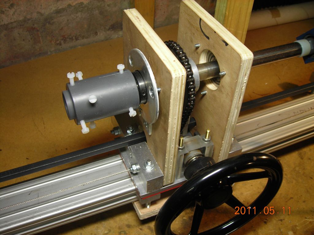
The bed of the lathe is a piece of 60mm x 40mm aluminum extrusion section which is very straight. The fixed headstock is a standard Sherline spindle unit, pinched from my Sherline mill. It's mounted rigidly on the bed and is raised up with a bit of 2" aluminium square box section and a Sherline riser block. The driving arrangement is a bit different here from proper glass lathes; the motor drives the fixed spindle directly, and the spindle then drives the square shaft, which drives the moveable spindle. This is instead of driving the square shaft directly, and then both spindles being driven from it. However, since I'm using an existing headstock assembly, there's no way around this. Alignment of the two spindles isn't absolutely critical, since each glass piece is usually held wrapped in a bit of padding (silicone rubber, glassfibre tape or similar) which allows for a bit of movement.
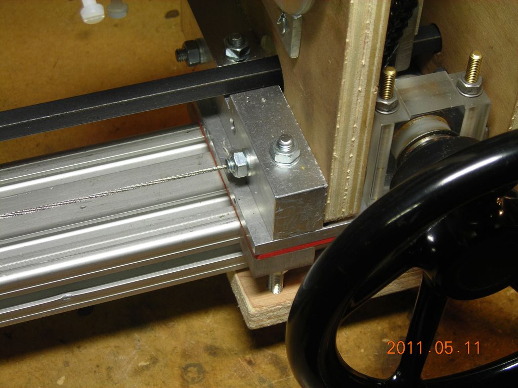
The moveable spindle is constructed from various bits and pieces. The shaft, which is hollow, is a piece of ¾" stainless-steel tube and rides in two flanged ball bearings. The bearings are mounted in pieces of thick plywood - this may not seem the most rigid arrangement, but it is sufficient. Forces experienced in a glass lathe are far less than in a similar metalworking lathe. The two plywood pieces are mounted on top of the carriage, which uses several plain bearings made from plastic sheet to slide on the aluminium rail. The carriage is moved using a handwheel attached to a small aluminium pulley, around which a length of 1.6mm diameter stainless-steel wire cable is wrapped. The ends of the cable are attached rigidly to the ends of the aluminium rail and tightened. A single loop around the pulley provides ample grip.
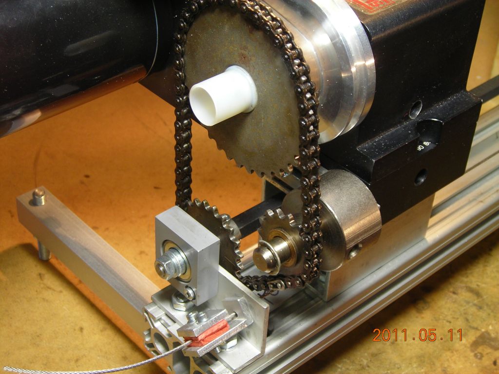
Coupling between the spindles is achieved using a piece of 8mm square steel bar mounted below the spindles. It is mounted in bearings at either end and is driven from the fixed spindle with a chain and sprocket drive. An identical chain and sprocket drives the moveable spindle. A square bush is mounted inside the sprocket on the square shaft and this allows the sprocket (and spindle) to be moved along the bed whilst maintaining coupling between the driveshaft and sprocket. I'm not happy about using chain and sprockets, as they are quite noisy; timing pulleys would be far better, but I already had two identical sets of chain and sprocket to hand, so I decided to use them.
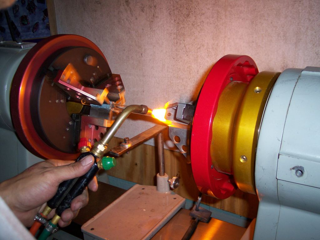
A connection for a blowhose is provided by a Festo pneumatic swivel coupling I found chucked out. It's the little blue cubical thing on the right of the photo below. It's basically just a couple of sealed ball bearings in a mount which provide a rotating airtight seal. Using this, it's possible to increase or decrease the pressure inside the work to inflate or deflate the glass at the joint. This is essential, because the molten glass will collapse from surface tension unless increased pressure is used to support it.
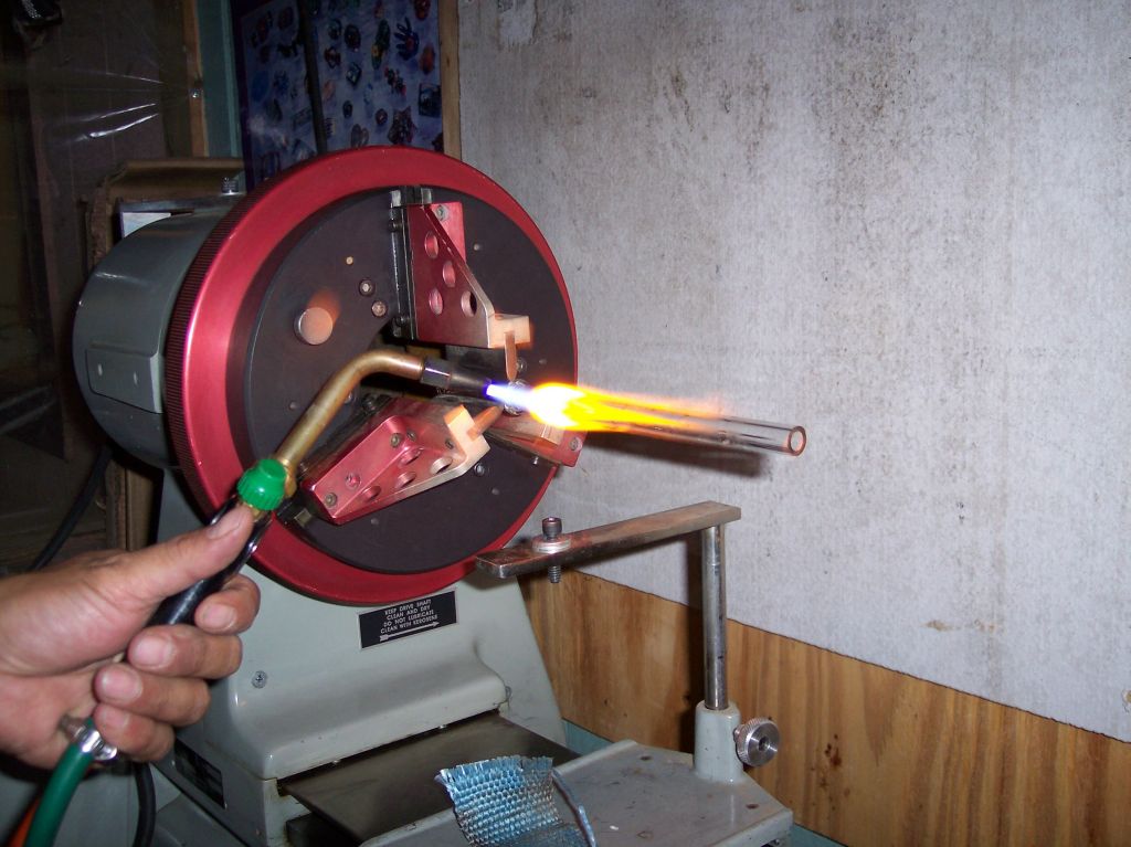
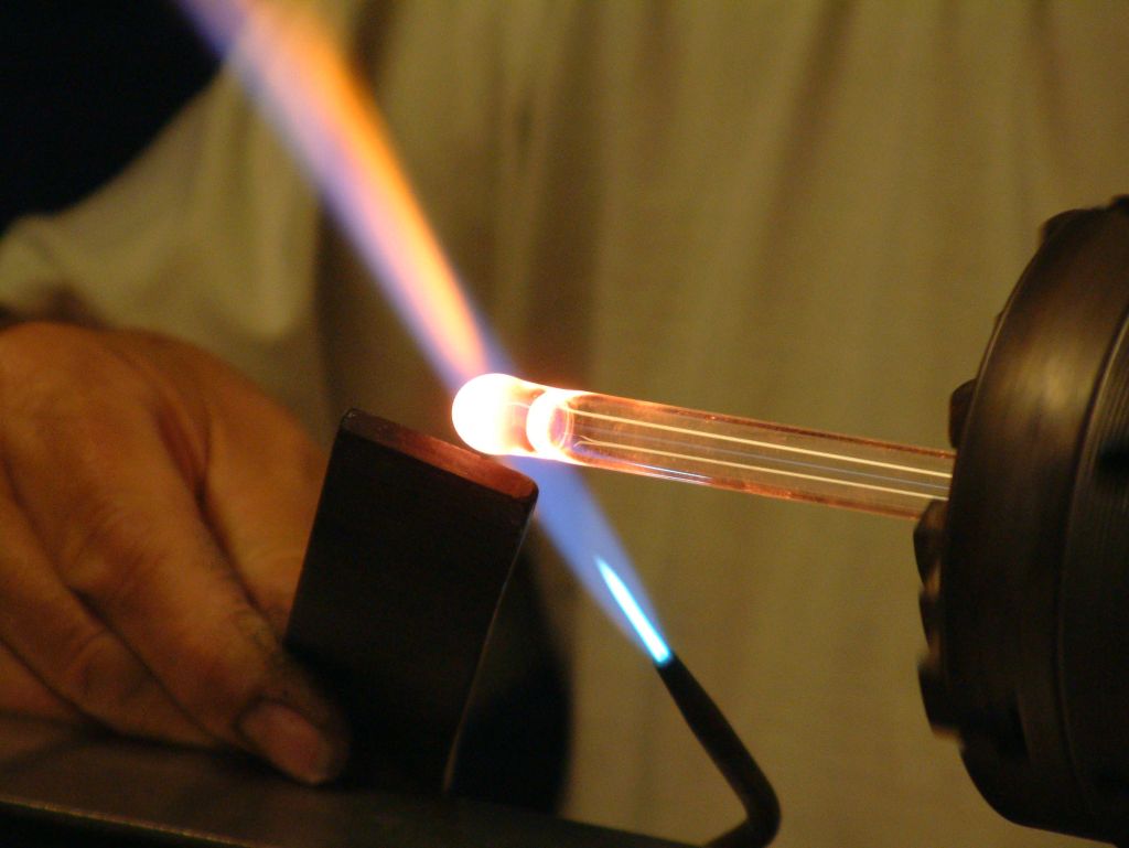
Joining glass tubing was surprisingly easier than I first expected - the ½"-¼" tubing join shown below was my very first attempt and it turned out pretty well!
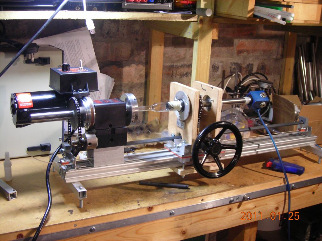 Overall view of lathe |
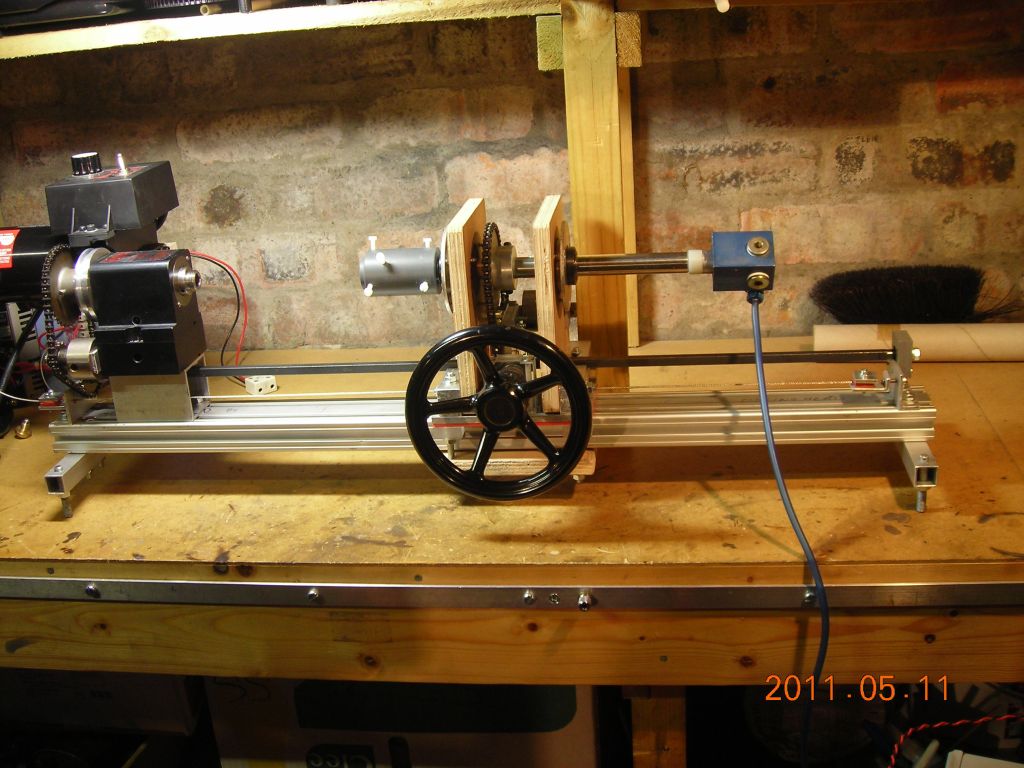 Another overall view |
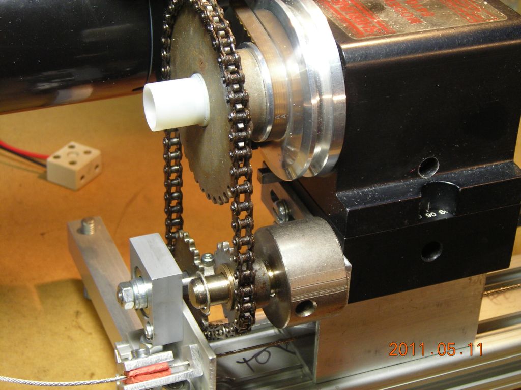 Closeup of drive arrangement showing idler sprocket and driveshaft sprocket |
 Another angle |
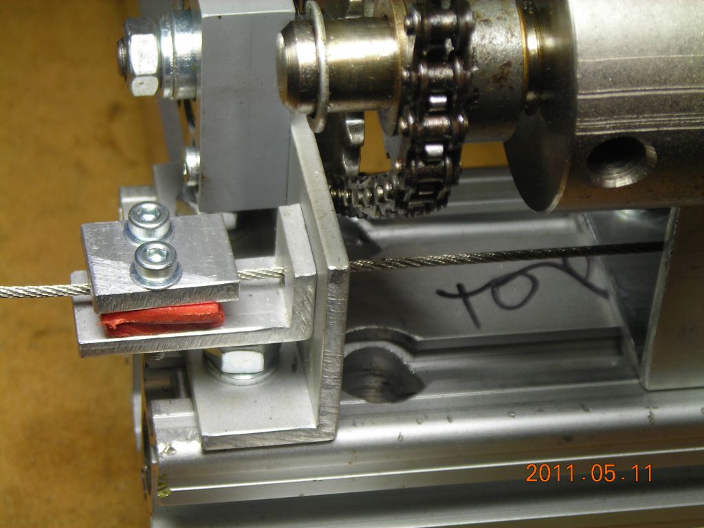 Left-hand clamp for steel cable used for moving carriage |
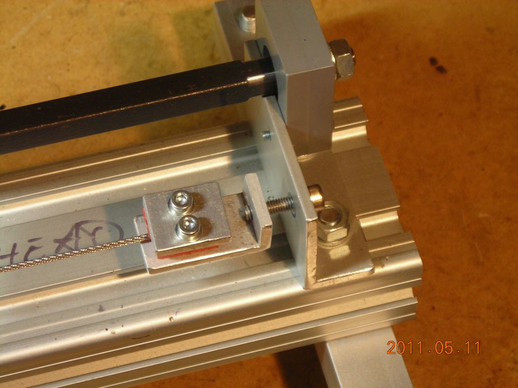 Right-hand clamp for steel cable, with tensioning screw |
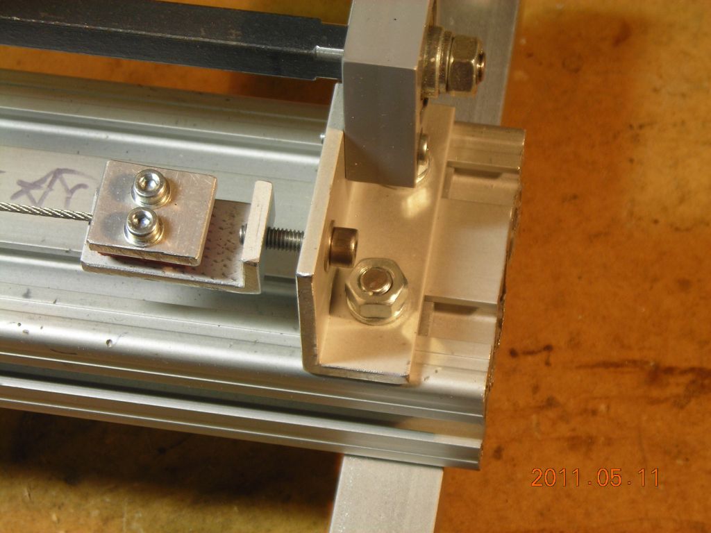 Another angle |
 Overall view of carriage. Two plywood pieces are used as vertical supports. |
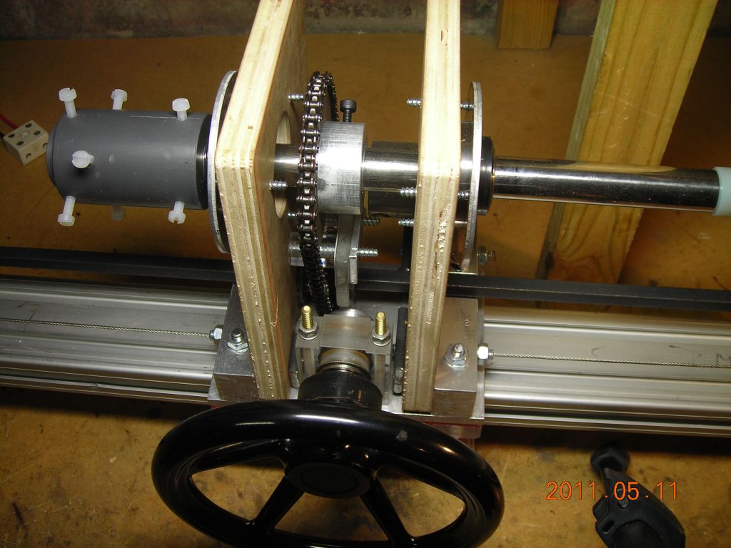 Another view. Sprockets are identical to those on the headstock. |
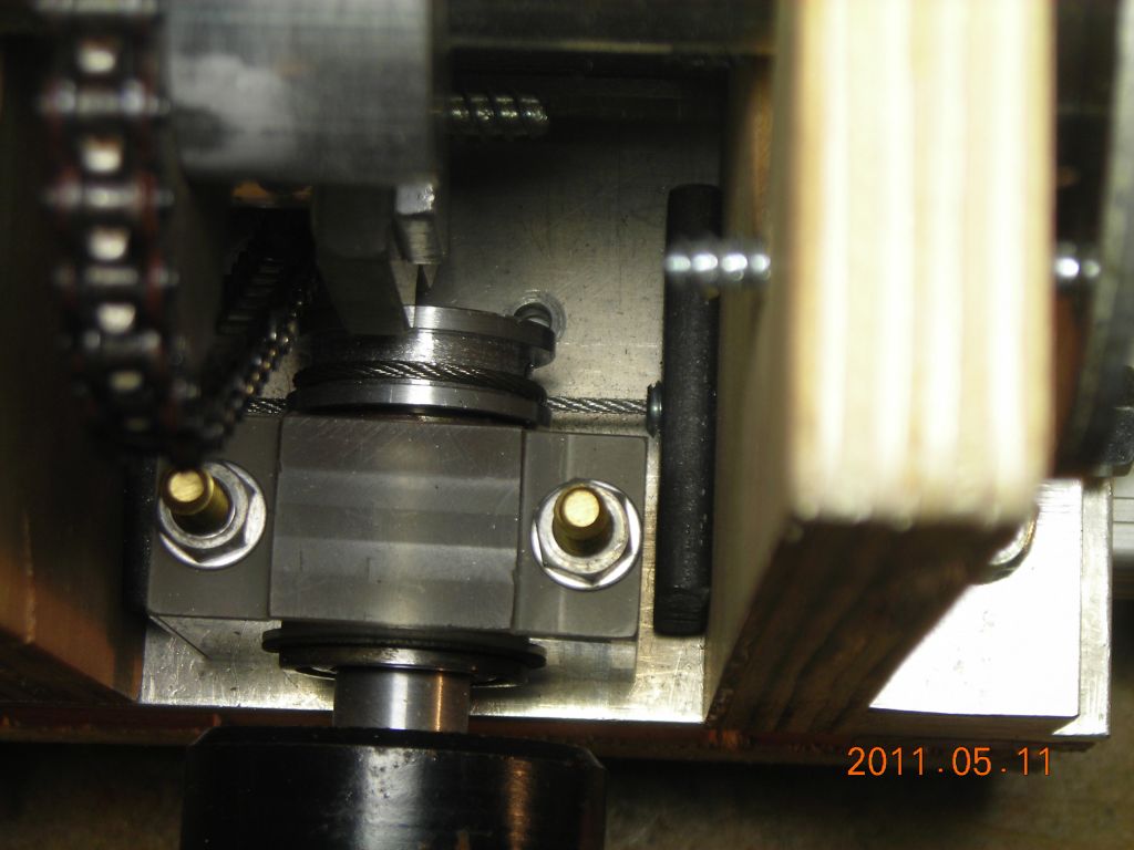 Steel cable wrapped once around winding drum, attached to handwheel |
 Cable enters through one of the bolts, there wasn't space to place it anywhere else! |
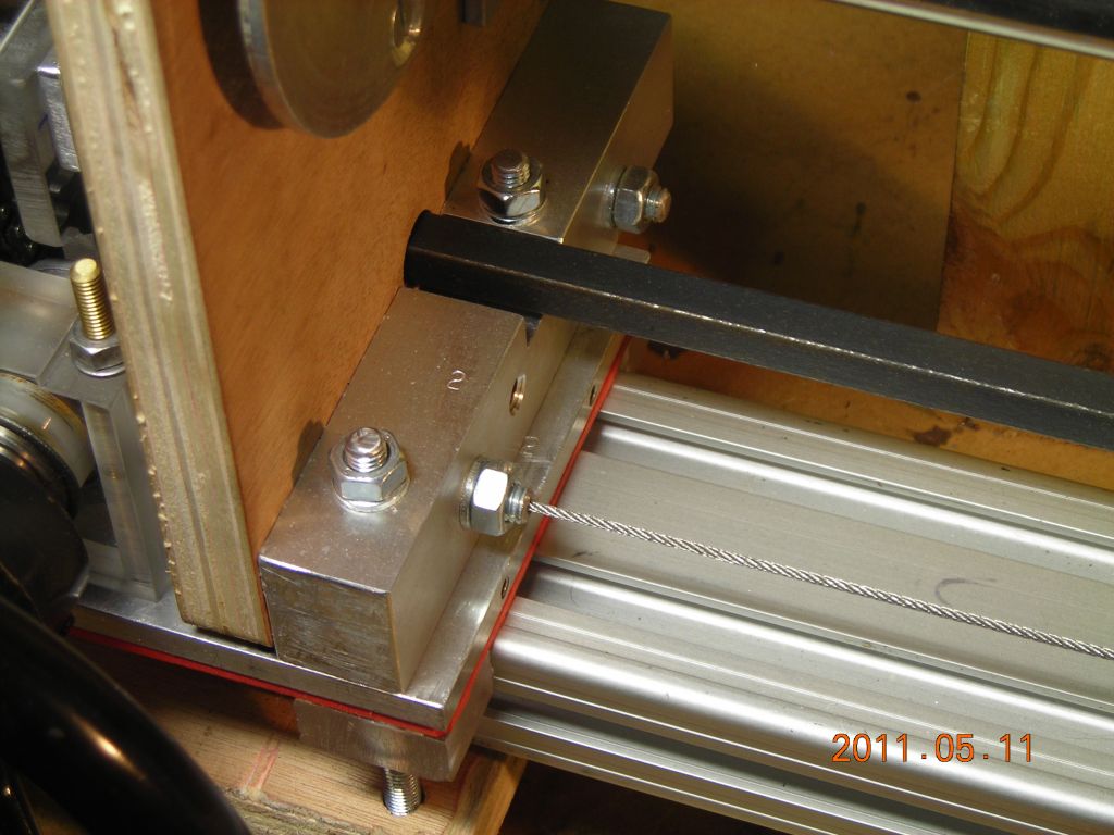 Cable exiting other side, again through one of the bolts |
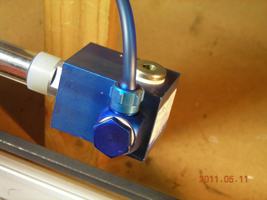 Air swivel for blowhose |
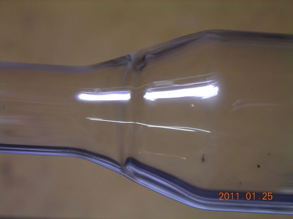 Closeup of join between ½" and 1" test tubes |
 Larger view |
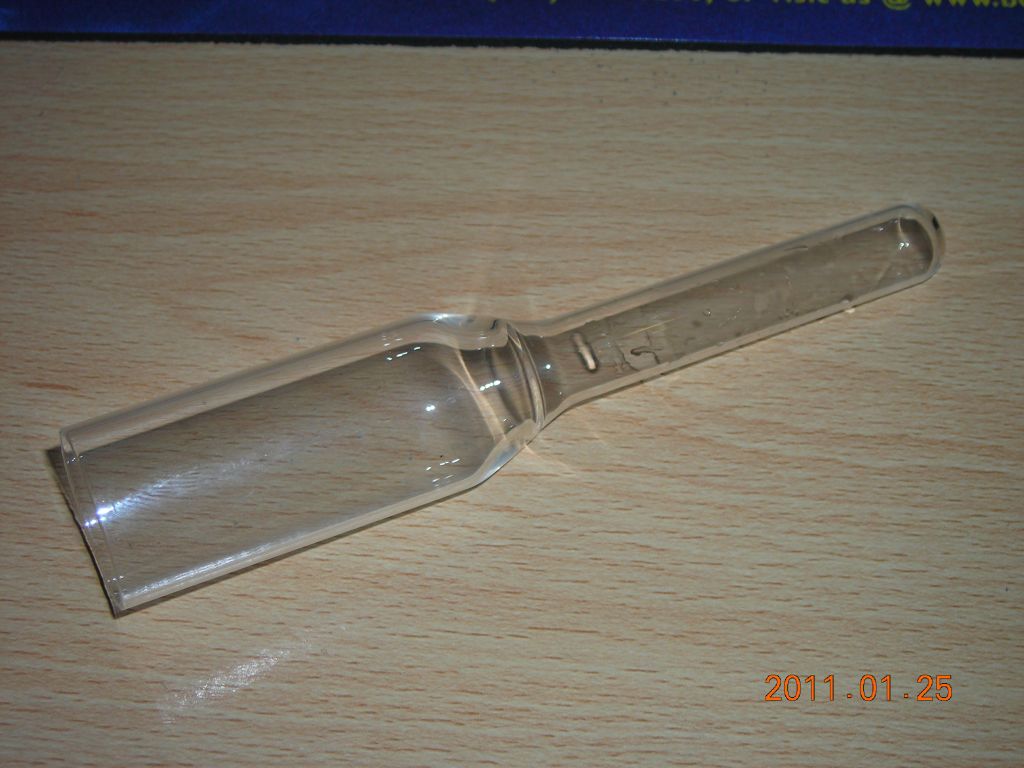
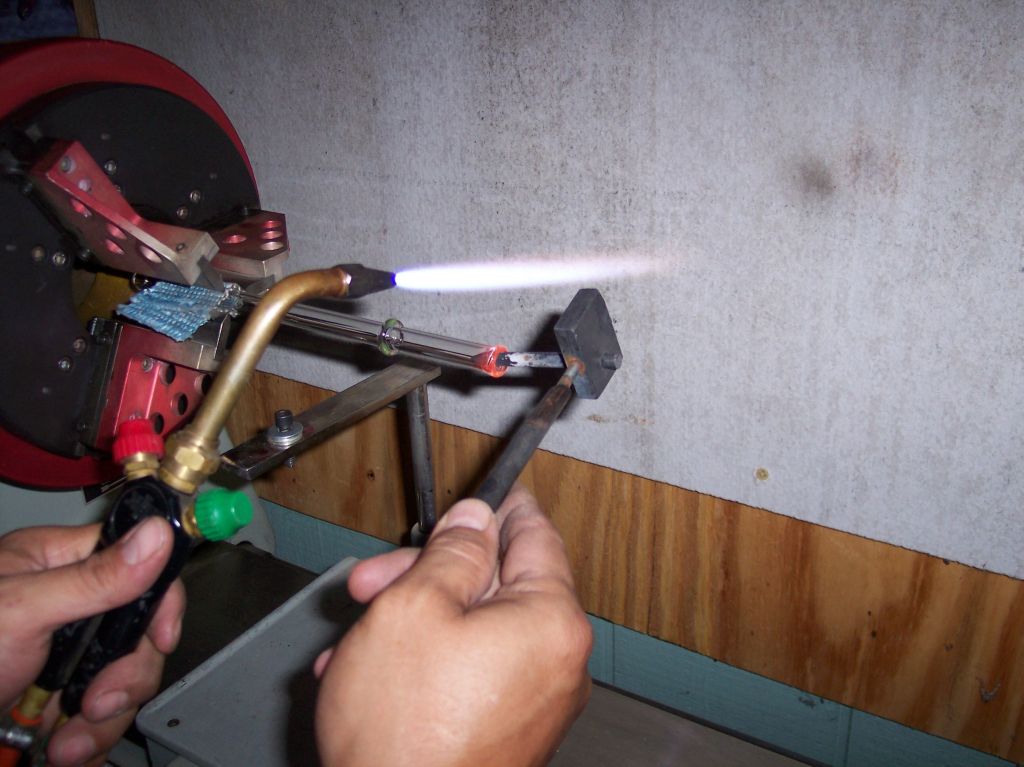
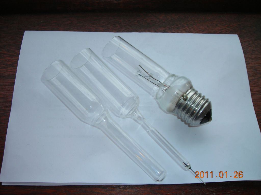 Some test joins - the one on the right is to a filament bulb base |
Some things I wanted to make involved using the base from a filament bulb for an electrical connection. The simplest way is to hold these by the metal cap. However, these often aren't stuck on straight relative to the glass of the bulb. I rigged up a simple universal chuck which can be adjusted until the glass itself runs true. A Sherline chuck is mounted on a ball-and-socket joint, which is then attached to a faceplate on the spindle nose. The base of the ball-and-socket can be slid across the surface of the faceplate and clamped in place.
I also made a bell chuck for the moveable spindle which allows 24mm diameter test tubes to be held accurately and an airtight seal to be achieved.
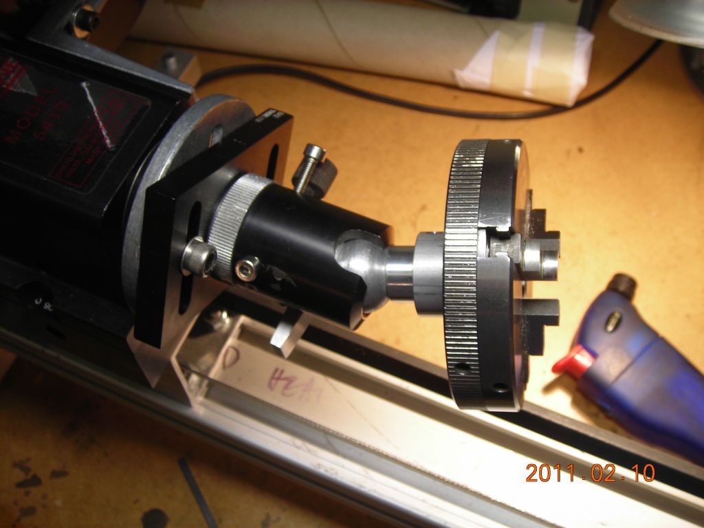 A "universal" chuck for holding off-center pieces. Very useful for cutting lightbulbs which often don't have the cap glued on parallel. |
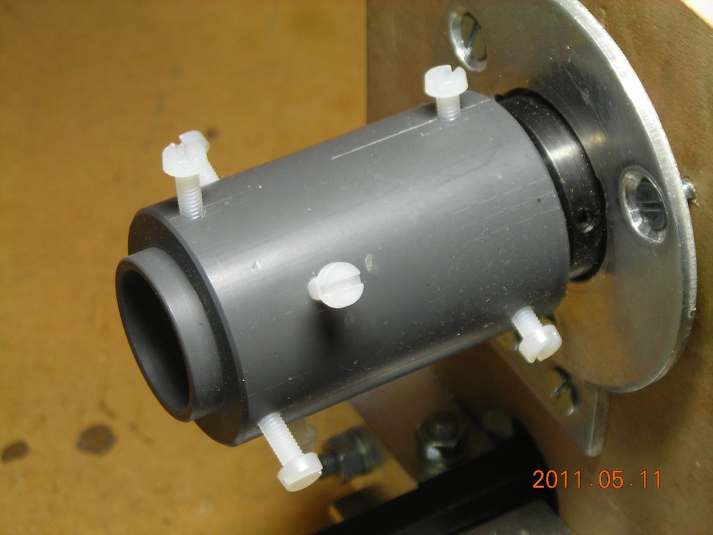 A bell chuck for holding 24mm test tubes |
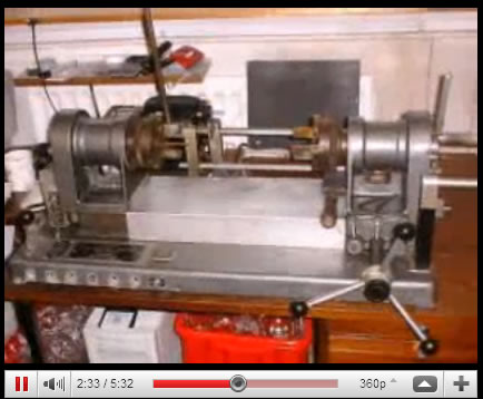
Here is a short clip of the lathe running when I was building it (the tailstock assembly wasn't built yet).
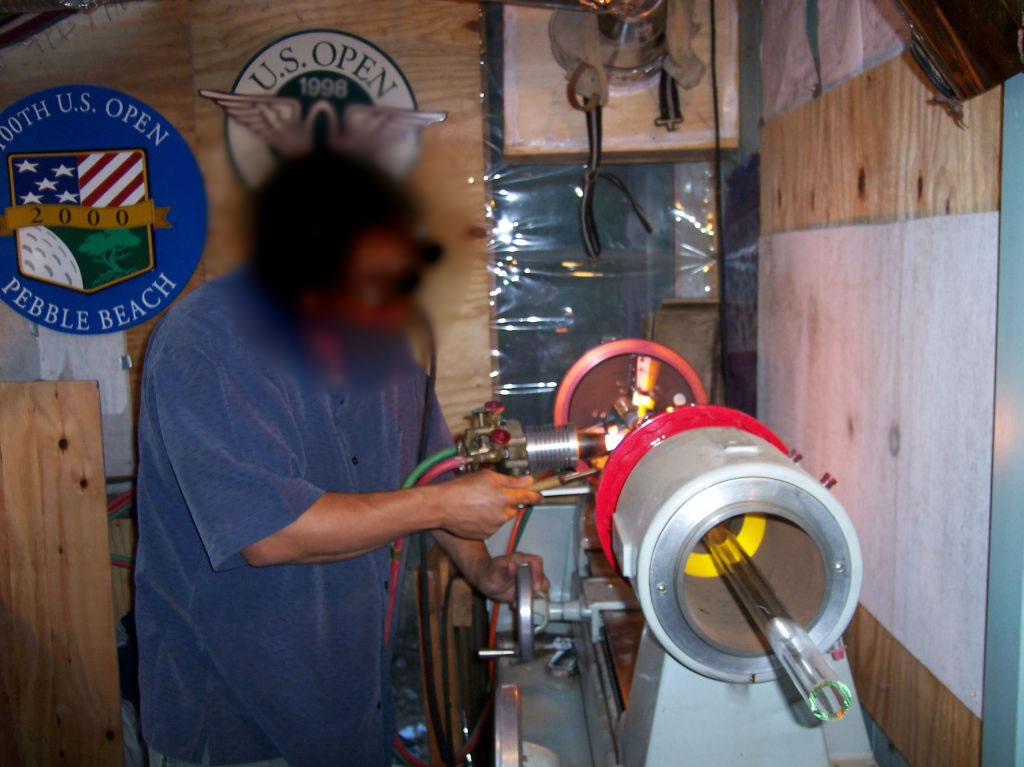
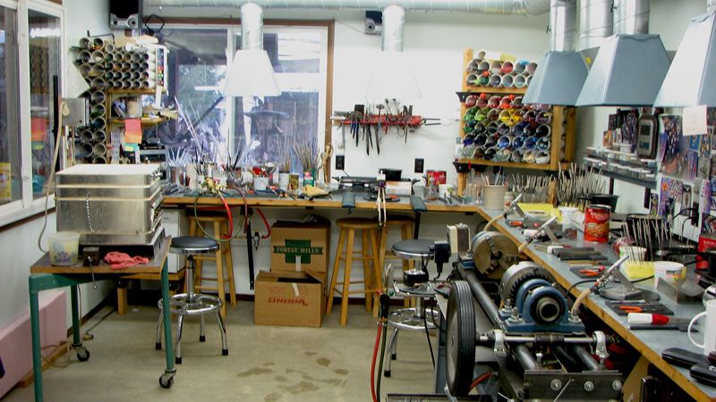
While designing my lathe, I looked around at other lathes for some inspiration. These are various photos from the web showing different types of glass lathes in use. I saved all these in a hurry, and I don't remember who the original sources are. Their copyright is with the original owner - if a picture is yours, my apologies; please drop me an email at lindsay@imajeenyus.com and I'll put a link to the original source!
 Nice big lathe, good view of hollow spindle |
 Closeup of both chucks |
 Good view of the chuck. Note the knife-edge clamps which actually touch the tube. |
 Flaring out the end of a bit of tubing |
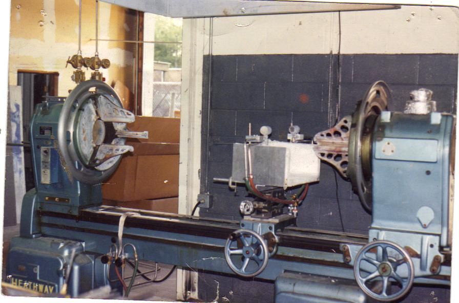
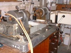
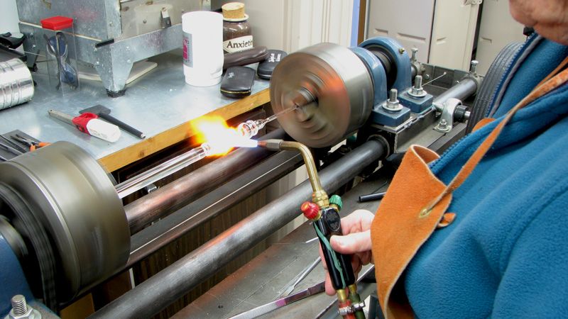 I like this one - seems to be home-built. Very solid construction! It uses normal lathe chucks and various standard ball-bearing blocks. |
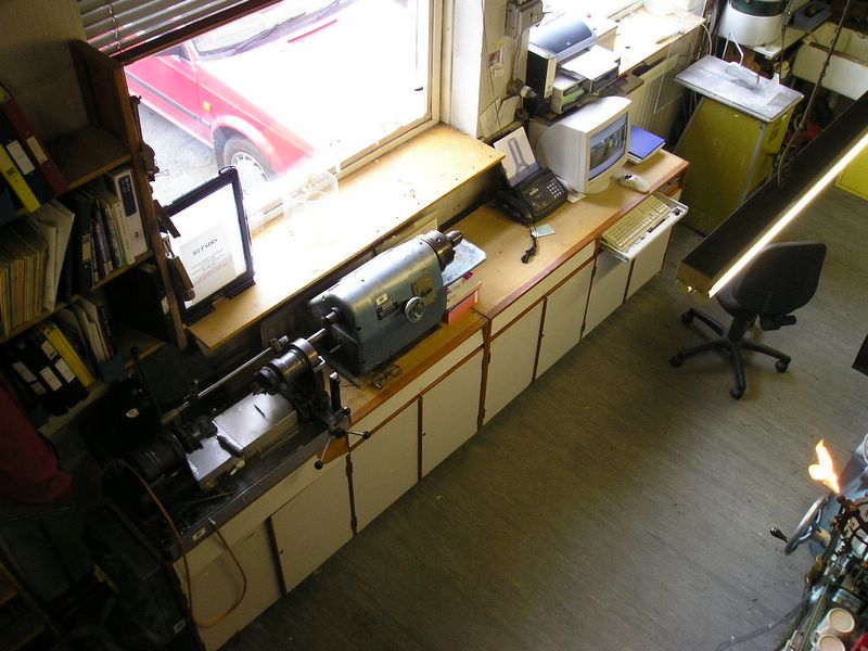
 Lathe down on bottom-left |
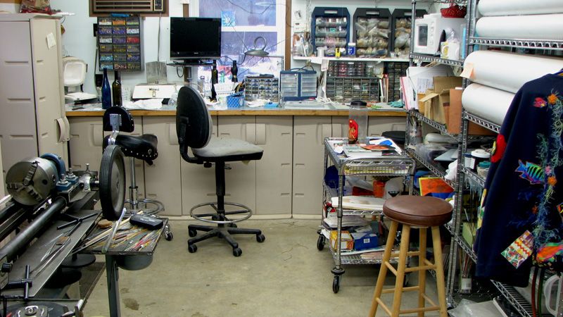
 You can see how it uses a wire wrapped around a hand-driven shaft (with big black wheel) to move the carriage - this is where I got the idea from for mine. I love the workshop! |
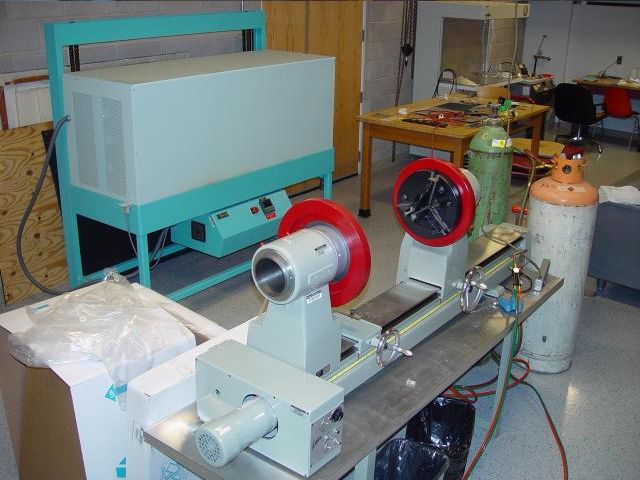
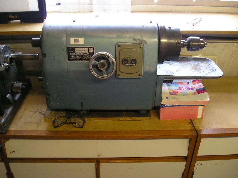
 It says "Heathway" but is much smaller than their usual lathes. Quite a nice solid little thing. |
 Blowing a bubble |
 Big Heathway lathe |
 Unknown model lathe. Good view of spindles and chucks. |
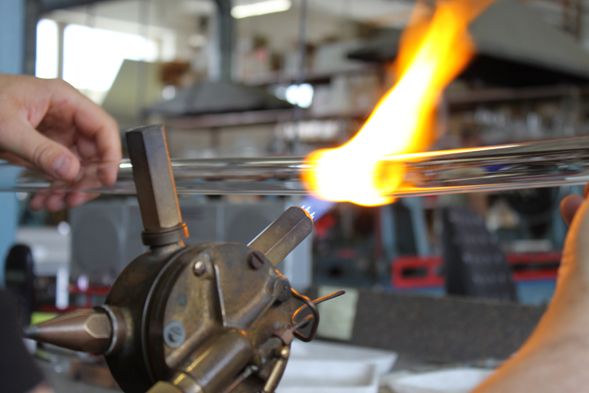 Not a glass lathe, but I really liked the design of this burner. It looks like each of the different tips can be rotated into position. |
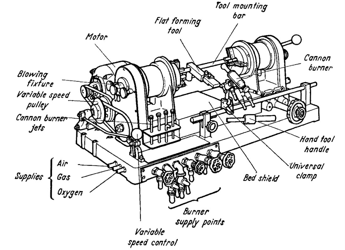
I came across a nice book called "Laboratory Glass-Working for Scientists", by A.J.B. Robertson. It's available as a PDF from the Sciencemadness library at http://library.sciencemadness.org/library/books/GlassWorking_OCR.pdf. Apart from containing a lot of useful information on glass-working techniques, it has a very interesting chapter on a small glass lathe. It has been especially designed for laboratory work, and has an amazing range of integrated tools, burners, holders etc. The chapter on the lathe is available here.
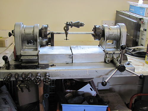
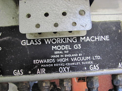
However, try as I might, I've been unable to find any more information on this beautiful little machine. I tried various people including Edwards Vacuum, the original manufacturers, and the British Society of Scientific Glassblowers, but never got anywhere. Purely by chance, I discovered that the glassblowing workshop at St. Andrews University had an Edwards G3 lathe, and I tried to buy it since the workshop was closing, but it was already sold. If anybody knows anything more about this type of lathe, has photos, or knows where one is in operation, I would be very glad to hear from you.
There are various pictures below of the lathes. The first two are from the book chapter, and the remainder are from the St. Andrews glassblowing website. Since the workshop is closed, the website may go as well, so I've mirrored these pictures on my site.
 |
 |
 |
 |
 |
 |
 |
 |
 |
 |
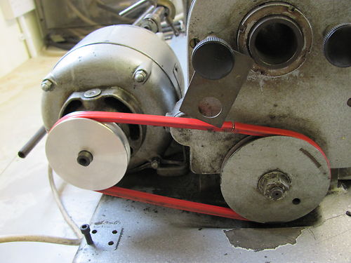
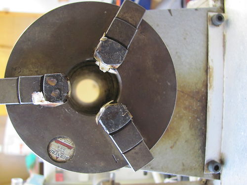
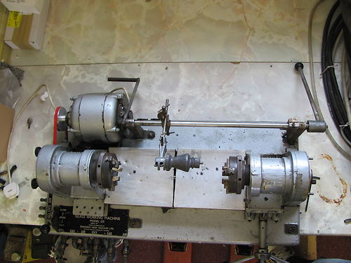
I was surprised to see an Edwards lathe listed on EBay - here are the photos from the auction. It's in much more complete condition than the St. Andrews one - all the gas valves are present, and the rear tool post is also there.
 |
 |
 |
 |
 |
David Knight is working on a glass lathe as well - check here for details: http://www.g3ynh.info/workshop/glass_lathe.html. The rest of his site is pretty neat too!
| ▲ Workshop |