| ▲ Workshop |
(In this, "CTE" = coefficient of thermal expansion)
"Solder glass" offers a means of joining glass pieces at processing temperatures far below the melting point of the base glass, thus avoiding the softening and distortion that would occur if the pieces were melted and fused together. This makes a wide variety of glass components and assemblies possible, since individual glass parts can be cut and finished accurately to size before the final joining process occurs. An example is flat panel CRTs, where the faceplate is often joined to the main tube body using solder glass. Other examples are vacuum-fluorescent displays and cuvettes.
Solder glasses are typically based on a mixture of lead oxide and boron trioxide (PbO and B2O3), sometimes with the addition of silicon dioxide. Boron trioxide imparts a low melting point, but exhibits a low expansion coefficient. The addition of lead oxide helps increase the expansion coefficient. There are more complex formulations which avoid the use of lead, but they are more expensive and more difficult to get hold of. As is often the case, the nasty stuff also happens to be the easiest to use.
I had previously tried looking for a Western supplier of solder glass, but never had much success. However, completely by chance, I later came across a Chinese company called Taizhou Sunflex, based in Hong Kong, who make several different kinds of solder glass. I fired off an email and received excellent help from them. Two weeks, and a little bit of money later, I was the proud owner of several hundred grams of two different solder glasses. The results of my experiments with them are described on this page.
I was sent two glasses - "TF-400" and "TF-490". The first melts at 400°C and has a CTE of around 7.2ppm/°, the second melts at 490°C and has a CTE of around 9.2ppm/°, both measured from 30°C-300°C. For full datasheets, see TF-400 and TF-490. Both are in extremely fine powder form, fine enough that dust floats in the air. It's therefore essential to wear a respirator when working with the powder, as both are leaded.
Since soda-lime glass, which is primarily what I'm working with, has a CTE of around 9ppm/° (specified from 30°C-300°C), I initially assumed that the solder glass should have a similar CTE. The chap at Taizhou had initially suggested the TF-400, but I said that this had too low an expansion coefficient and requested the TF-490 instead. As it turned out, he sent some of both glasses. This was extremely fortunate, because it turns out my understanding of CTE matching was wildly wrong, and, in fact, the TF-400 was a good match to soda-lime glass! This apparent conundrum caused me a lot of confusion, until I did some experiments to understand exactly what was going on.
I'll show first some examples of my attempts before I learned which glass to use.
I initially tried a small pile of TF-490 on a microscope slide and heated it over a bunsen flame. It melted nicely, and formed a slightly opaque blob on the glass with excellent adhesion. I then tried joining a flat end window to a piece of test-tube glass. The TF-490 powder was mixed up into a thick paste with some Bullseye "Glastac" glue (this glue burns off cleanly during firing, leaving no residue, and is widely available from glass fusing suppliers) and the paste was applied in a fillet between the test tube and the flat window. It was fired at 510°C in the kiln for about 15min and allowed to cool inside the kiln. When I took it out, the solder glass had flowed nicely, forming a neat fillet between the two bits of glass.
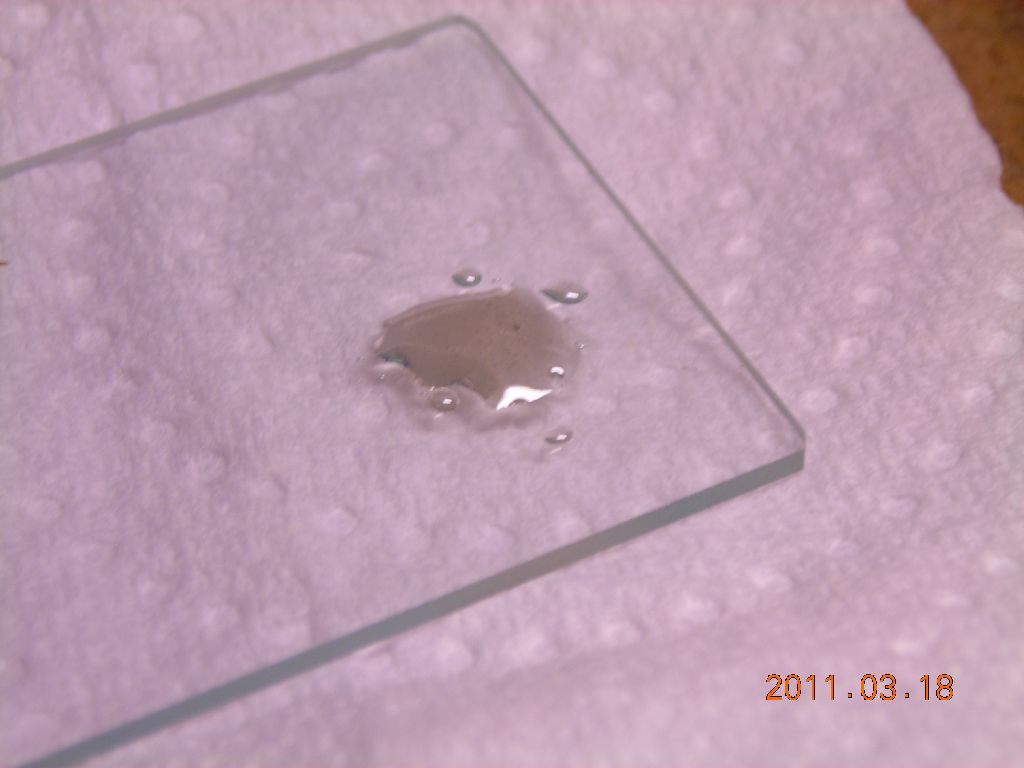 Pile of TF-490 on a microscope slide |
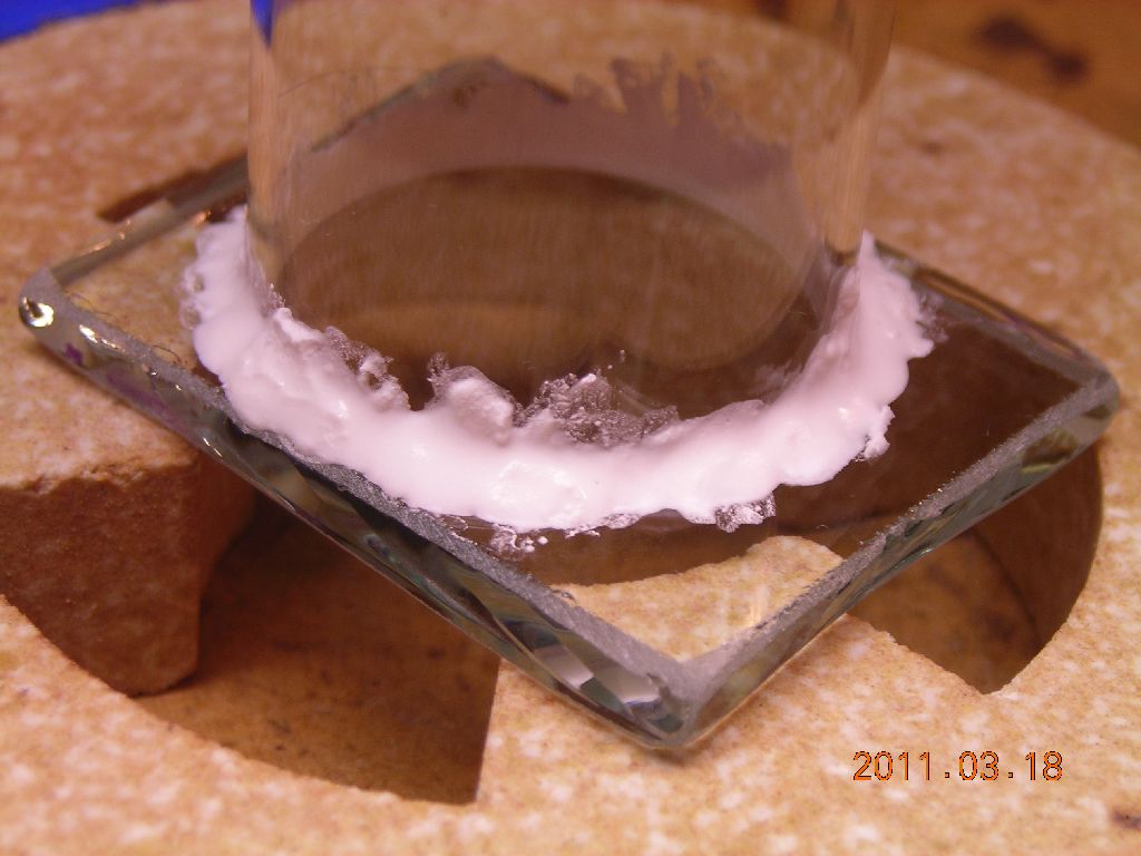 TF-490 paste in Glastac applied around edge of test tube |
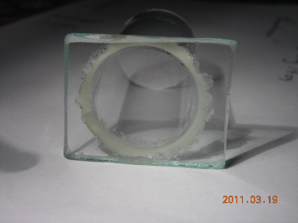 Bottom view after fusing |
 Side view. Note nice fillet. |
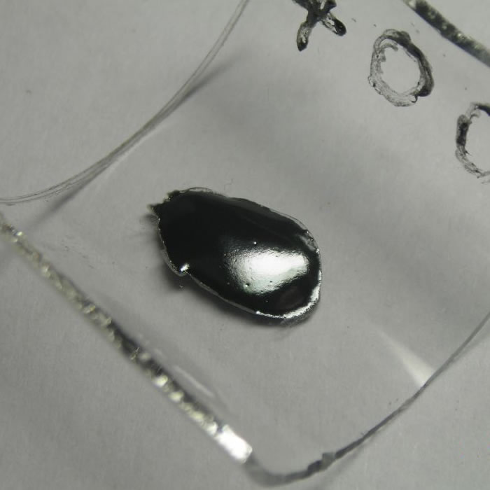
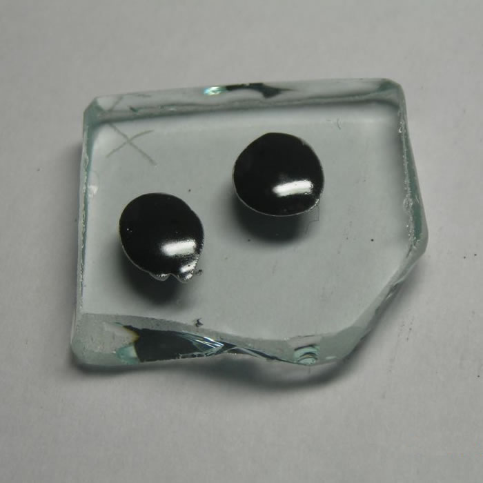
I also tried various mixtures for applying lettering and decoration to glass. I made up various mixtures of both solder glasses and different metallic oxides with Glastac glue, and painted them on to a microscope slide. You can see the results below.
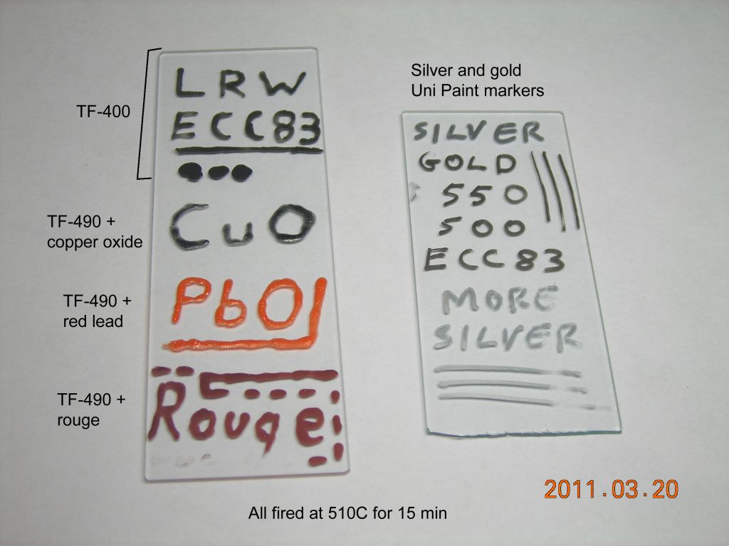 Various solder glass mixtures fired on to microscope slides |
The TF-400 went very well, and did not need any additional colouring, as it's already greyish. Of the rest, the mixture of TF-490 and red lead was the best. It gives a nice bright orange colour and has excellent adhesion to the glass. All these were again fired at 510°C for 15min.
The microscope slide on the right with the silver and gold marks was a test of some Uni Paint Markers. These were also fired at 510°C and surprisingly show pretty good adhesion, although it can be scraped off with a fingernail. The silver remains shiny, but the gold turns a dark brown.
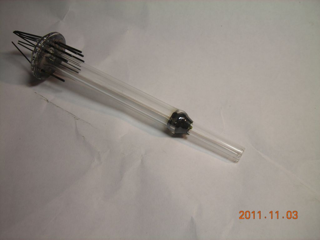
13/04/11: Joining CRT stems. I have had trouble before trying to join CRT stems to soda-lime glass tubing, probably because the CRT stem glass is leaded and has a slightly different expansion coefficient to soda-lime glass. The seals cracked, and another problem was the pins in the base moving as the glass softens. I discovered that it's possible to join the CRT stem nicely to a piece of test-tube glass by using the solder glass. There are a couple of photos below.
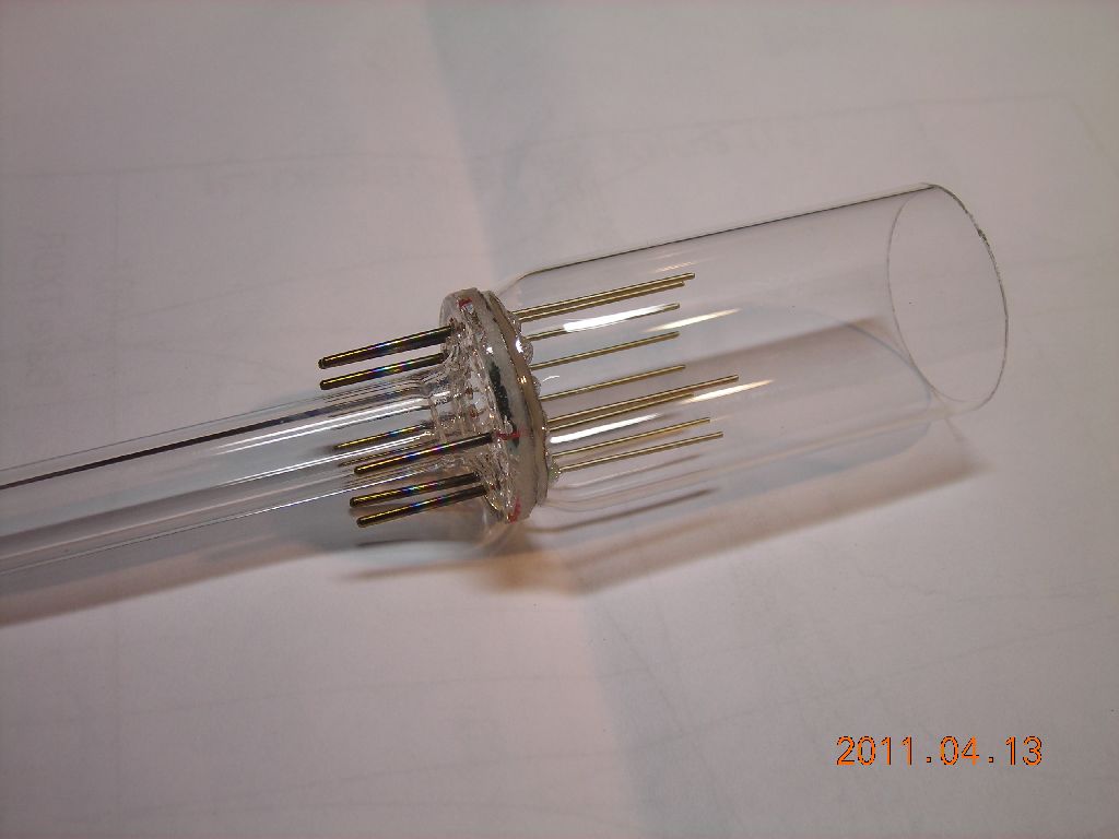 CRT stem attached to test-tube glass |
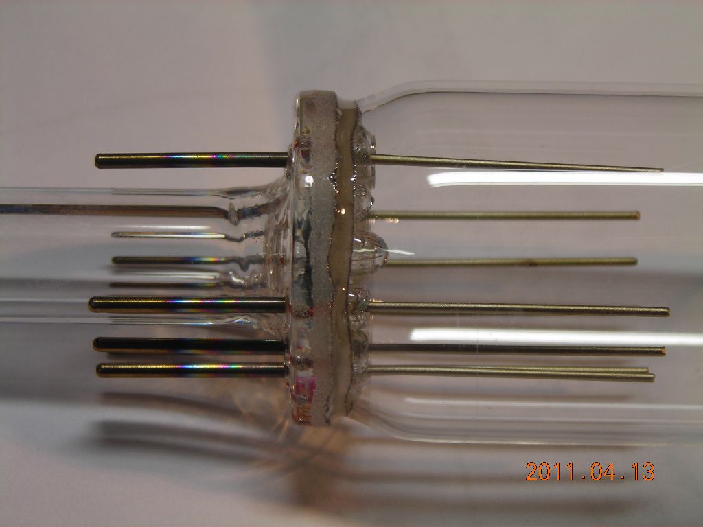 Closeup of join showing the solder glass fillet |
The test-tube glass was necked down so that the CRT stem could sit on top when placed vertically. A ring of TF-490 solder glass paste was first applied to the rim of the CRT stem, then it was squashed down on top of the test-tube glass and placed in the kiln. It was first dried at about 80°C for ½hr and then fired at 510°C for 15min. After firing, it was left to cool down naturally over several hours. A nice fillet of glass has formed between the two parts and forms a very strong joint.
This has many benefits over actually fusing the glass, so I'll probably stick to this when making vacuum devices using CRT stems.
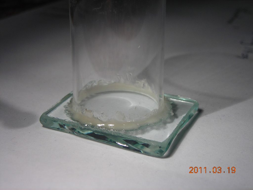
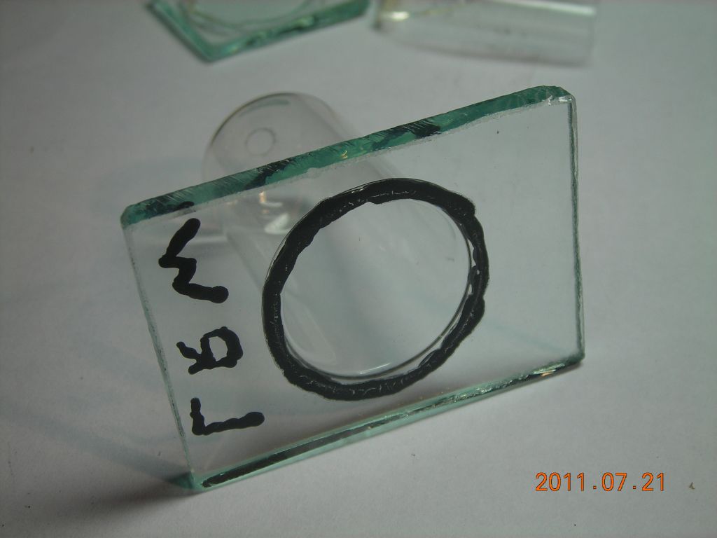
I had thought that everything was going well, until I discovered that the sample I'd done of the test tube joined to float glass had cracked around the base - see below. The solder glass remained attached to the edge of the test tube, but had pulled away a sliver from the float glass.
 Cracked join |
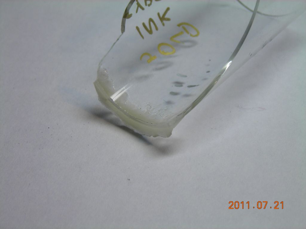 Closeup of test tube end |
I asked the manufacturer about this and he suggested trying the TF-400 glass instead. I decided to do a thorough investigation to find which glass is suitable.
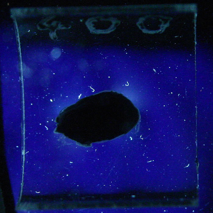
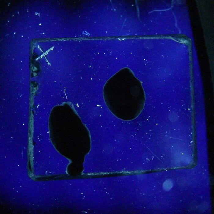
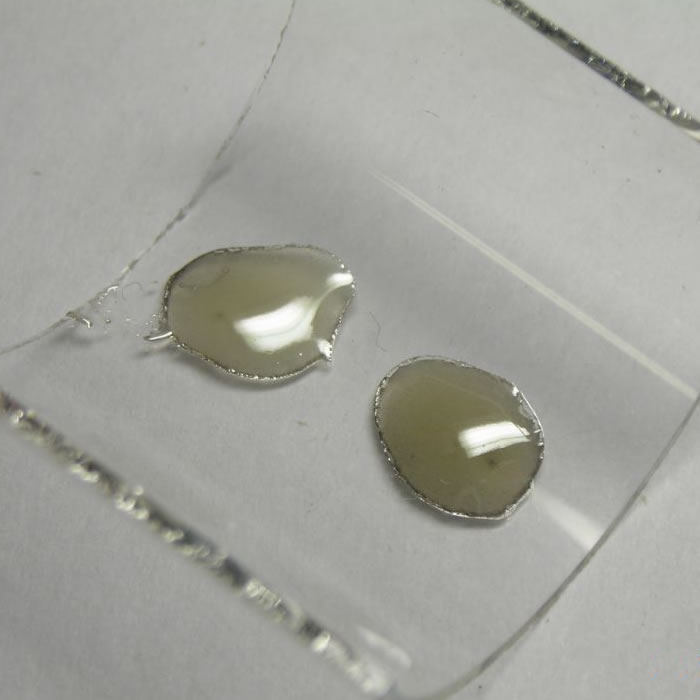
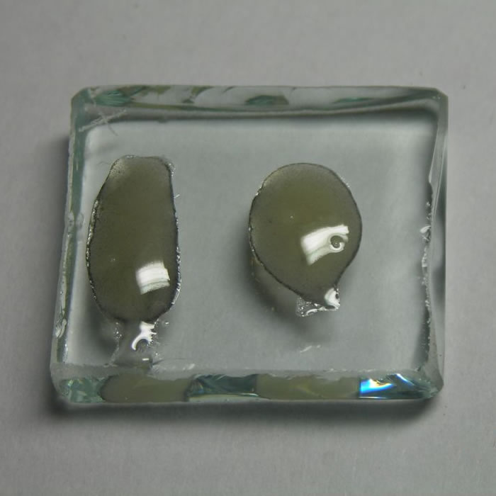
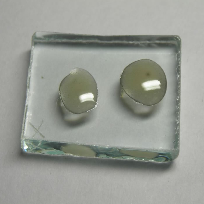
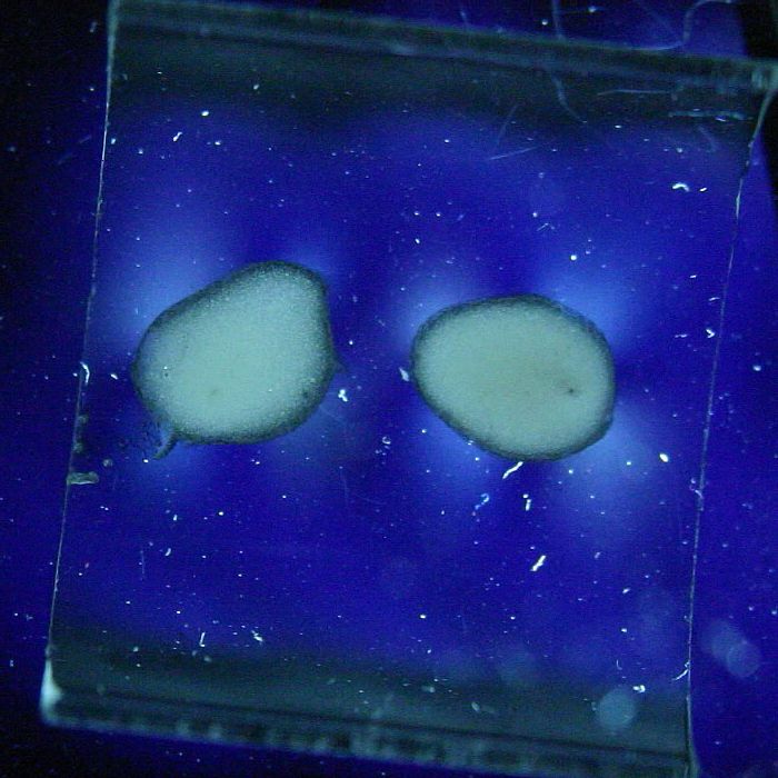
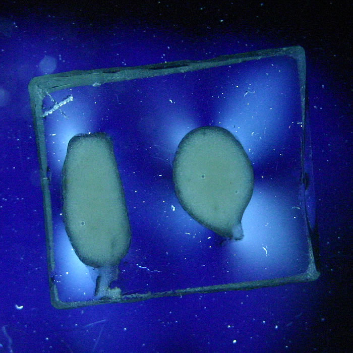
11/06/11: First of all, I made up some test samples of the solder glasses on various base glasses. The base glasses used were a halved test tube, and both sides of 4mm float glass. I decided to check both sides of the float glass because I wondered if the issue of one side having a tin layer (from the manufacturing process) was affecting adhesion of the solder glass. One side of the float glass is indicated with an "X" - this is arbitrary, as I don't actually know which side is the tin side.
So, in total, we have the following six samples:
Glastac was used as a carrier medium for both solder glasses. TF-400 was fired at 430°C for 30min, and TF-490 was fired at 510°C for 30min. Both were cooled at 200°C/hr to room temperature. Photos of the strain patterns were taken through crossed polaroids with a CFL lamp as illumination. Shutter speeds were constant throughout.
 |
 |
 |
|
 |
 |
 |
 |
 |
 |
|
 |
 |
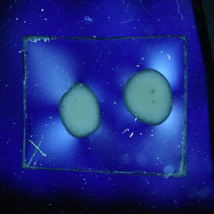 |
Obviously, the TF-490 glass is not a good match to any of the soda-lime glass I'm using. The TF-400 is much better and results in lower strain patterns.
Here is a combined photo of all the strain patterns:
 |
14/06/11: I next tried looking at the strain patterns at elevated temperatures to see if the strain increased or decreased with increasing temperature. The results were mostly inconclusive - the only interesting (but totally expected) point was the TF-400 strain patterns. A very slight strain appeared up to about 310°C, above which it disappeared as the TF-400 went above its glass transition temperature. Apart from that, nothing very interesting. I did have a whole load of pictures of the strain patterns on this page, but I've removed them since they don't really add anything.
08/07/11: So, here is the problem. TF-400 is a good match to soda-lime glass, but the expansion coefficients say it shouldn't be. Just to remind you, TF-400 is around 7.2ppm/° while soda-lime is typically around 9ppm/°, specified from 30°C-300°C. I decided that the only way to fully understand what is going on would be to measure the thermal expansion curves of the different glasses and actually measure their expansion coefficients. This requires the use of a dilatometer so I, aherm, built one. The dilatometer is a very long story which I won't go into, but here are some brief details. It's a horizontal instrument, taking samples 10mm long by about 5mm diameter. The housing and pushrod are made of fused silica, and the sample is heated with a small tubular oven which can reach a maximum of 600°C. The maximum measuring range is ±150μm. It was calibrated using a fused silica sample which I assumed had a constand expansion coefficient of 0.55ppm/° over the whole temperature range (not too badly off, considering I'm measuring CTEs in the 7-9ppm range anyway). All temperature ramps were at a rate of 5C°/min and started at 30°C. It has its problems, but I think it's good enough to make a conclusion as to why TF-400 is a better match.
Before we look at the proper results, a brief word on the typical form of an expansion curve. The graph below is actually for the TF-400, but is typical of most glasses.
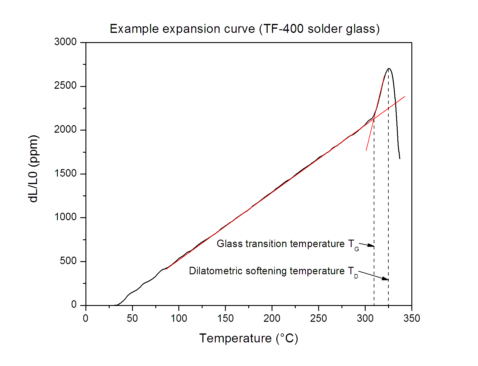 |
The horizontal axis is temperature, and the vertical axis is the expansion of the sample in ppm from its initial length at 30°C. For example, if the sample was initially 10mm long at 30°C, and has expanded by 0.01mm at 300°C, the dL/L0 is 1000ppm. To obtain the coefficient of thermal expansion between 30°C and a certain temperature, we divide the dL/L0 value at the higher temperature by the difference between the higher temperature and 30°C. In the previous example, if dL/L0 is 1000ppm at 300°C, then the CTE between 30°C and 300°C is 1000/(300-30)=3.7ppm/°.
The expansion is reasonably linear up to a temperature called the glass transition temperature, TG. Above this, the expansion increases until it reaches a peak at the dilatometric softening temperature, TD, above which the expansion reverses (it starts shrinking). Above TD, the glass begins to soften, hence why the sample appears to shrink under the force of the dilatometer pushrod. The range between TG and TD is the annealling range. Although the glass is solid within this range, internal stresses are able to disappear by holding the glass for a while at a temperature in this range.
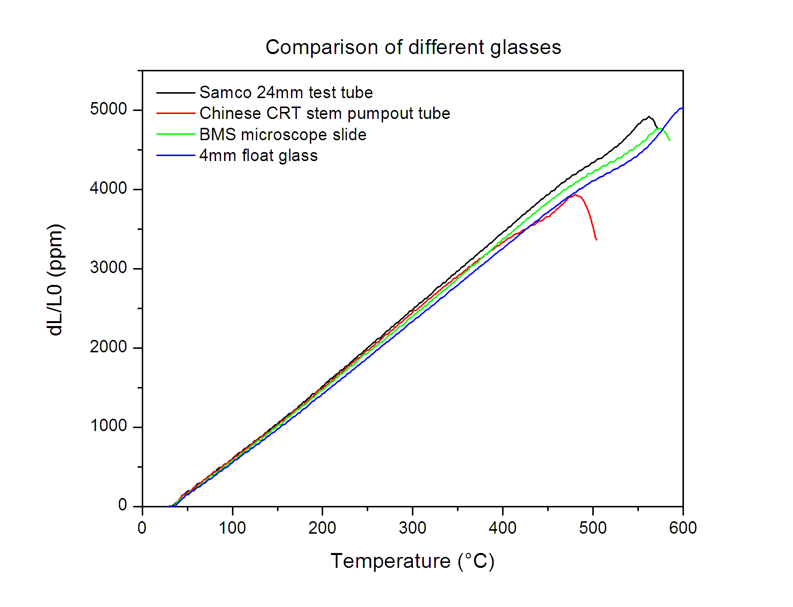
Now for some proper results. The graph below is a comparison of four different types of glass. All have a very similar CTE (30°C-300°C) (see table further down for a summary of all properties). However, note the much lower TG and TD of the CRT stem tube. This indicates that it is leaded glass, not soda-lime glass. Also note that the peak of the CRT stem tube curve lies below most of the curves for the soda-lime glasses. This suggests that it would be difficult trying to fuse leaded glass directly with soda-lime glass, because the expansion coefficient measured from 30°C to the TD of the leaded glass is lower than that for the soda-lime glass and hence there would be a mismatch.
 |
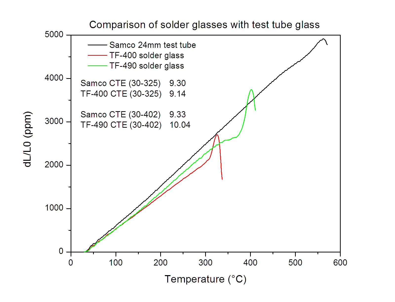
A similar argument can be used to explain why TF-400 is a good match. The graph below shows the curves for both solder glasses and for the test-tube glass. Note how the peak of the TF-400 curve lies very close to the soda-lime curve, whereas the peak of the TF-490 curve lies above it. By comparing the CTEs measured between 30°C and the TD of the respective solder glass, we can see that the CTEs of soda-lime and TF-400 are a very close match (9.30 and 9.14) whereas the CTEs of soda-lime and TF-490 are poorly matched (9.33 and 10.04).
 |
In conclusion, although it may appear initially that the suitability of glasses can be determined solely based on their CTE from 30°C-300°C, this is not true. What is far more important is the CTE of both glasses measured between 30°C (or whatever low temperature point is chosen) and the lower TD of the two glasses used, because it is at this temperature that the joint will solidify during the cooling process. Because the CTE from 30°C to TD will always be higher than the CTE from 30°C to 300°C, a suitable solder glass will have an apparently lower CTE than the base glass to which it is being joined. In a similar vein, although the comparison isn't exact, metals suitable for sealing into soda-lime glass, such as 52 Alloy, have a slightly higher CTE from 30°C-300°C.
Here is a summary of the properties of the various base glasses and solder glasses. There is some doubt as to the TG of the base glasses because of the dip in the curve before TG is reached. I'm not sure why this happens and it may be an anomaly of the dilatometer. However, my main aim was to compare the curves for the solder glasses with those of the base glasses, and the dips in the base glass curves don't affect any of the conclusions.
| Tg (°C) | Td (°C) | CTE 30°C to 300°C (ppm/C°) | CTE 30°C to Td (ppm/C°) | |
| Samco 24mm test tube | 500-520 | 561 | 9.2 | 9.26 |
| Chinese CRT stem pumpout tube | 400-450 | 480 | 9.07 | 8.72 |
| BMS microscope slide | 500-550 | 574 | 8.88 | 8.76 |
| 4mm float glass | 500-550 | 598 | 8.65 | 8.84 |
| TF-400 solder glass | 309 | 325 | 7.6 | 9.15 |
| TF-490 solder glass | 350-370 | 402 | 8.39 | 10.04 |
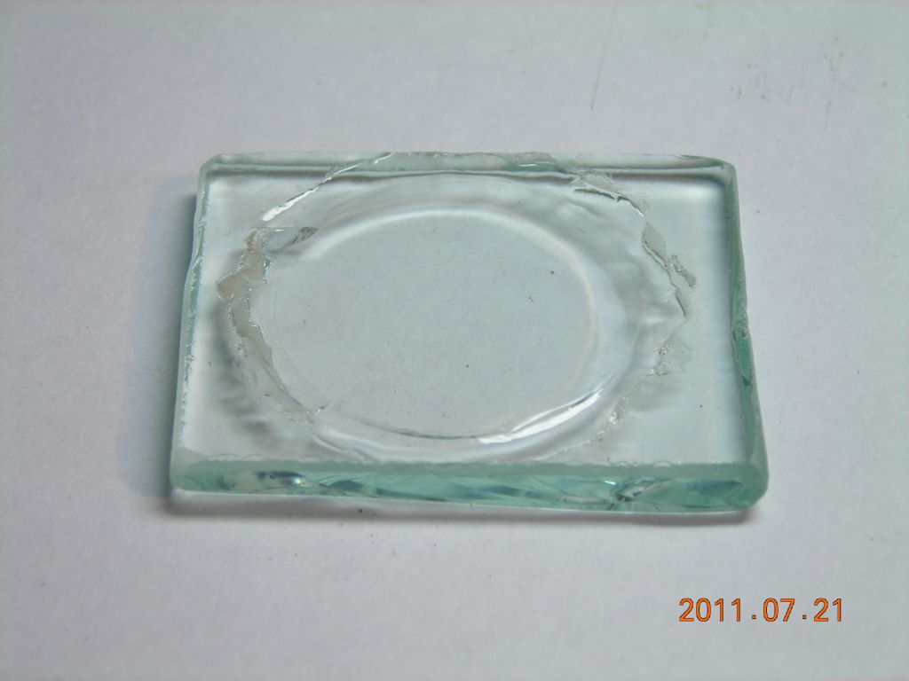
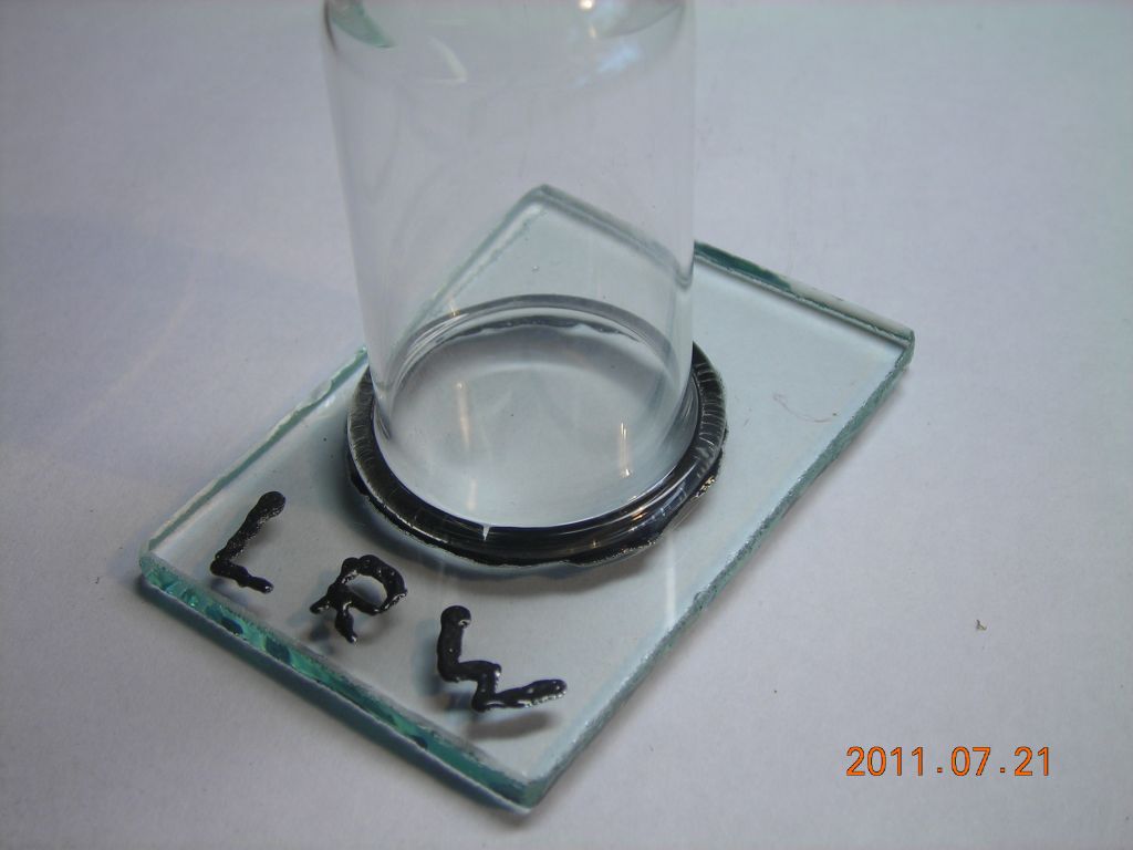
Finally, here is an example of a joint made between a flanged test tube and some 4mm float glass using the TF-400 solder glass.
 |
 |
03/11/11: Here's another example of its use. I was curious to see if it was possible to fire it with a gas torch instead of a kiln. It seems to work pretty well. Here, I wanted to attach a short piece of 6mm OD soda-lime tube to the 9mm leaded tube on a CRT stem (the 6mm tube is easier to seal off). I flared the CRT stem tube out slightly so the 6mm tube fitted inside it, applied some solder glass paste and fired it with the torch. Forms a very nice joint! What's more, it might be possible to dismantle it again by heating.
 |
 |
If you look closely at some of the expansion curves shown above, you'll notice a slight dip just before Tg. I worried that this was something to do with the instrument, but it looks like it's due to poor annealing of the sample. I happened on a very interesting document from RWTCH-Aachen which shows exactly this effect. The relevant page is available here on my site, or the original document is available here on their own website. It's part of a four-part course on basic materials science of glass, and the other lectures are great material as well. See the main page at http://www.ghi.rwth-aachen.de/www/pages/glas/basis_wk_glas/index-de.html.
If the glass has been poorly annealed, as a result of fast cooling, then it will contract slightly as stress is released, just below the glass transisiton temperature. This is the reason for the slight dip in the expansion curve. Theoretically, if I had run the sample again, the dip should have disappeared because the sample is now annealed. As to why the samples should have had stress in the first place, I can only imagine that the act of cutting them from larger pieces of tubing or plate somehow created stresses in the small sample. The solder glass samples were made from compacted pellets, melted inside a metal mould which was machined away later, so I could see some stress being caused by the contraction of the metal around the glass. In sort, make sure that any samples are well annealed before trying to measure thermal expansion.
| ▲ Workshop |