| ▲ Electronics |
28/02/18: Check out This Old Tony's video on trying to make an ultrasonic knife from an ultrasonic cleaner!
25/03/17: I was able to measure the peak-to-peak displacement of the horn at resonance (about 20 microns) - see bottom of page.
21/02/17: I've finally done a video about the whole transducer measurement and tuning process - see the bottom of this page.
30/11/16: Kevin at the YouTube channel TheBackyardScientist has done an awesome video of using an ultrasonic cleaner to sonicate champagne and other fizzy drinks!
09/11/15: This guy is attempting to produce ammonia by using a sort of "ultrasound-assisted" Haber process. Well worth a read!
The circuit described here (i.e., a voltage-fed inverter connected directly to an ultrasonic transducer) will probably be happy driving low-powered transducers, below about 100W. However, as I've read more about ultrasonic transducers and driving circuits, I've realised that there are problems using this circuit for higher powers.
The proper electrical model for an ultrasonic transducer is a capacitance in parallel with an LCR series resonant circuit. The fixed capacitance corresponds simply to the electrical capacitance of the transducer, neglecting mechanical oscillation effects. The LCR circuit corresponds to the resonant behaviour of the transducer. Therefore, if the transducer is connected directly to the output of a voltage-fed inverter, the bridge transistors will charge and discharge the fixed capacitance, resulting in large current spikes at the switching transitions. For small transducers, this isn't really a problem because the transistors can handle the spikes, but it becomes a problem for larger transducers.
To get around this problem, you need to use a matching network to adapt the electrical properties of the transducer to something that the inverter is happy driving. Matching networks come in many different forms, but the most common are LC and LLCC. Do a Google search on them and you should find some useful results.
Some interesting suppliers of ultrasonic transducers and related equipment:
On this page, I describe the construction of a power supply for a 70W ultrasonic tank transducer, and the machining & tuning of an aluminium horn. I originally started all this in order to do ultrasonic drilling, but could find no simple, cheap means of driving high-power transducers. "Proper" ultrasonic horns are usually made from titanium, and the power sources are usually fancy affairs with auto frequency tuning. However, I found that, for the power levels I'm interested in, an aluminium horn works perfectly well, and it is possible to drive the transducer with a manually-controlled oscillator and inverter. I won't go into too much detail on the principles behind piezoelectricity and these kind of ultrasonic transducers - I assume you know a bit of background since you're reading this.
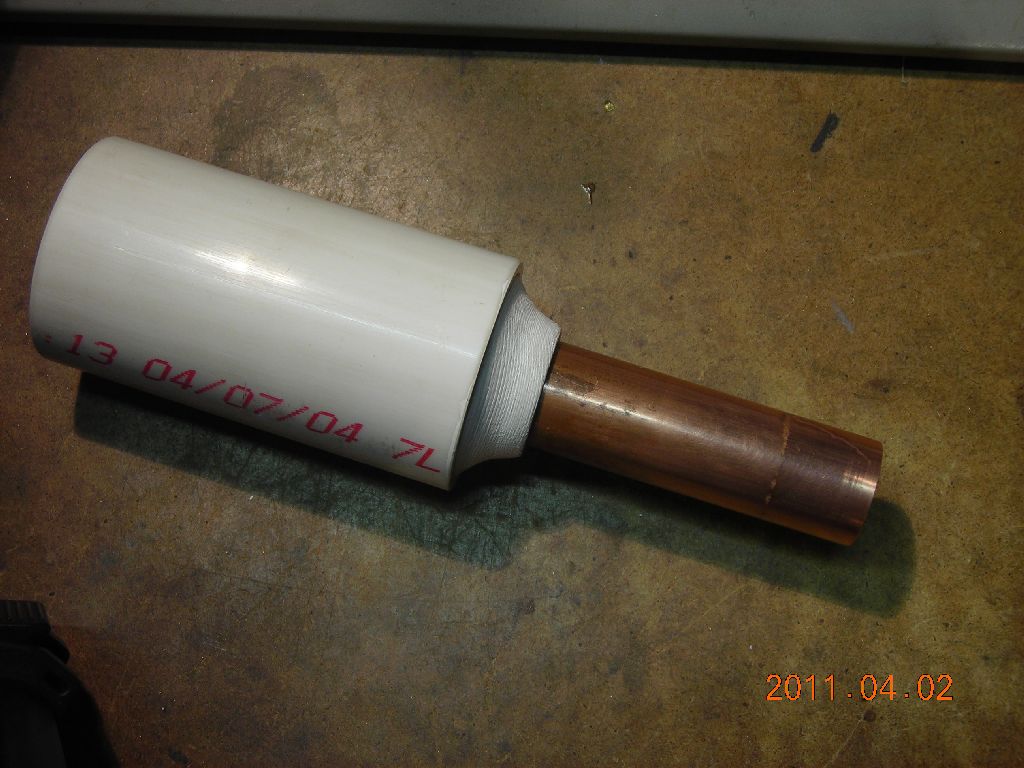
I'm using a 28kHz, 70W bolt-clamped Langevin transducer (part number SMBLTD45F28H) which was bough from Steiner & Martin (http://www.steminc.com/) a few years ago for around $30-$40. For photos of it please scroll down or see their website. These are typically intended for ultrasonic cleaning, sonochemistry, low-power welding etc. On the surplus market, they can sometimes be found inside cleaning tanks.
An ultrasonic transducer is a lump of metal and ceramic which has a particular resonant frequency. To operate the transducer at resonance, it must be driven with a high-frequency AC signal. Voltages for power ultrasonics are typically high, in the hundreds of volts. The best way of determining the resonant frequency is to plot an impedance spectrum of the transducer. This is usually done with very expensive network analysers, but it can also be done with a simple USB oscilloscope and sweep frequency generator, if the oscilloscope software has suitable capabilities.
The circuit used is shown below. "Drive" comes from the output of a sweep frequency generator. "Current sense" goes to the USB oscilloscope. In the example I'm giving here, the sweep parameters are a linear sweep from 20kHz to 60kHz in a time of 100ms. The generator has a trigger output at the start of the sweep which is used to trigger the USB oscilloscope. If we assume that the drive voltage stays constant (i.e. the transducer doesn't load the output of the generator significantly), then we can determine the impedance of the transducer from the magnitude of the current signal.
 |
I'm using PicoScope software (http://www.picotech.com/picoscope-oscilloscope-software.html), version 5. This has the ability to overlay successive traces to form an "envelope" of the waves. If we do this with the current sense waveform, we get the first picture shown below (this has been contrast-enhanced). Although the scope can't pick up individual cycles because of the very slow scan speed (100ms), it can record the amplitude of the waves, shown by the envelope of the black area. We can then use WinDig (http://www.unige.ch/sciences/chifi/cpb/windig.html) to digitise the envelope. When using WinDig, instead of entering the oscilloscope time for the horizontal axis (100ms to 200ms), we enter the frequency range that the scan covers (20kHz to 60kHz). This results in a "spectrum" showing the amplitude of the current at different frequencies. Finally, it's a simple matter to work out the impedance of the transdcuer from this, shown in the second photo below. Note the logarithmic vertical scale.
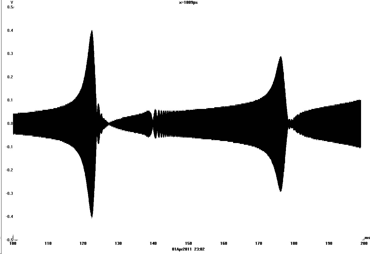 Waveform in oscilloscope software |
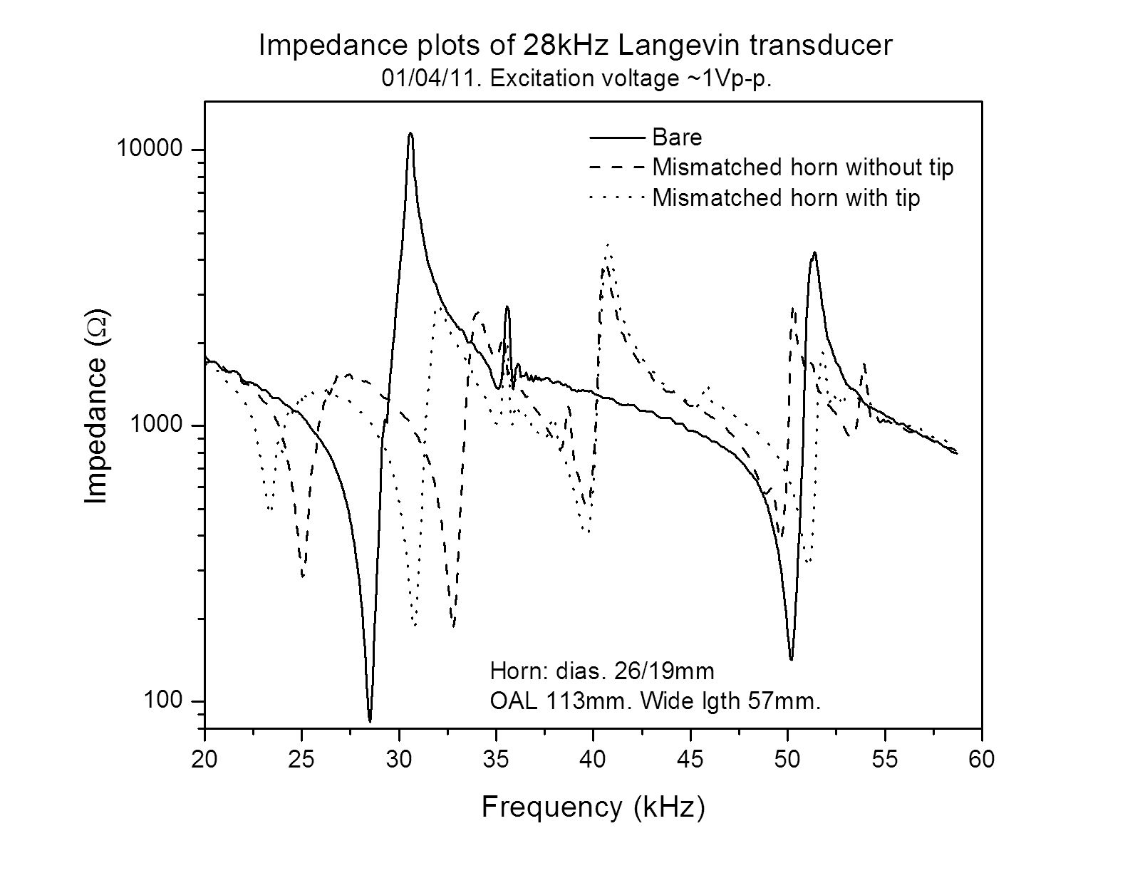 Calculated impedance spectra |
There are three plots shown. Take the one of the bare transducer. At about 28.5kHz, the impedance drops to a minimum. This is the mechanical resonant frequency, and is where we want to drive the transducer. This resonance appears like a series LC electrical resonance to the driving circuit. Current and voltage are in phase. Just above, at about 31kHz, there is an anti-resonance. This has a maximum impedance, and appears like a parallel LC electrical resonance. At higher frequencies, 50kHz, another resonance appears, again followed (52kHz) by an anti-resonance. These higher resonances correspond to other, weirder vibration modes of the transducer and we're not interested in them.
Now notice the effect of adding a mismatched horn, both with and without a tip (still referring to the second picture above). This was a piece of aluminium I'd machined before to totally the wrong dimensions - I only show it out of interest. The fundamental resonance with the horn present is lower than that of the bare transducer. Also, the impedance at resonance is higher, meaning that less power can be supplied to the transducer. Note also that, the further away from the bare transducer resonance, the higher the impedance with the mismatched horn and tip. Conclusion: for optimum power transfer, the resonant frequency of the horn must be matched to that of the bare transducer. This can be guessed roughly, as the horn should be ½ a wavelength long, but generally horns are made longer and machined down whilst measuring the resonant frequency, in order to tune them exactly. This is what I attempted to do here, with some success.
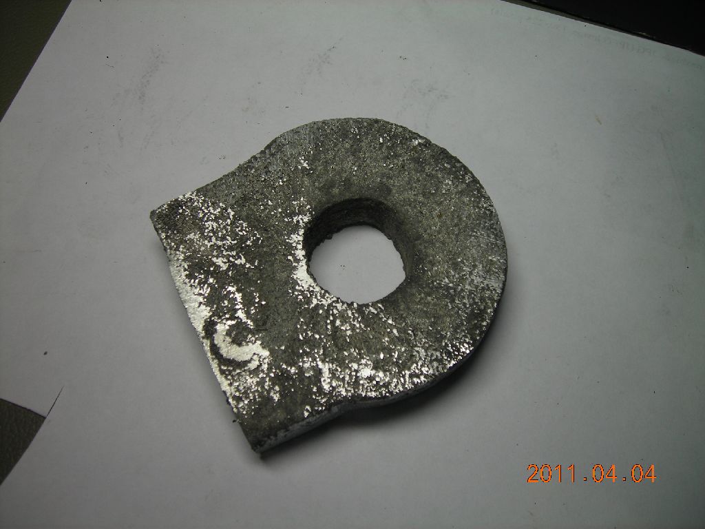
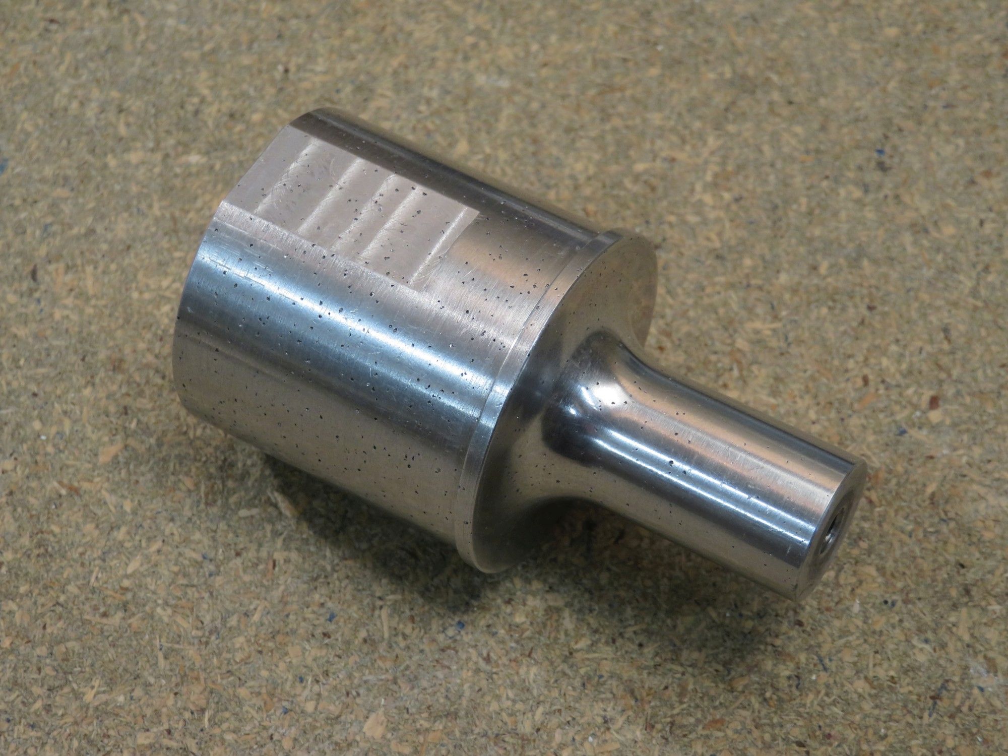
I decided to cast an aluminium horn. I wasn't entirely sure if a casting would work satisfactorily, but I didn't have a piece of aluminium bar big enough at hand. So, I made up a quick pattern from some lengths of pipe, and then cast it in aluminium in a sand mould, using the electric melting furnace.
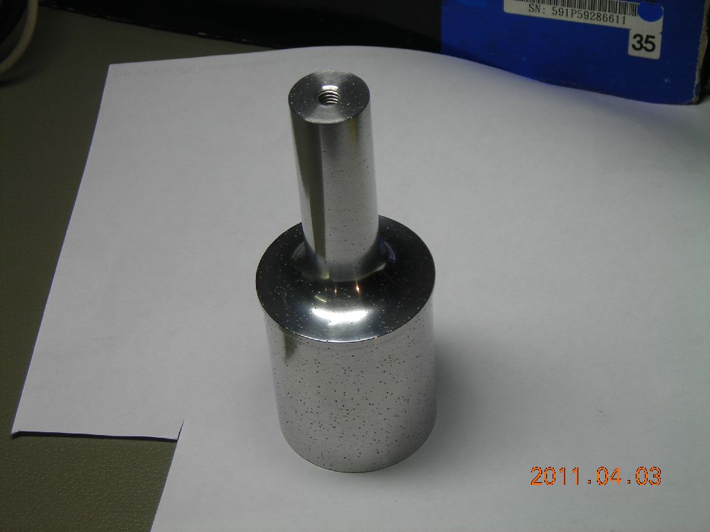
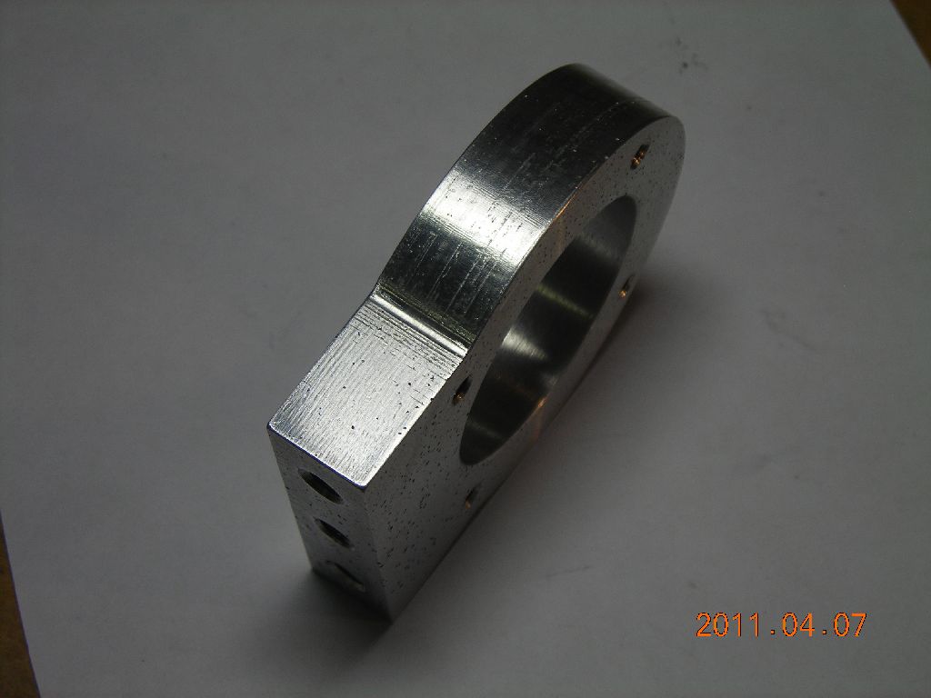
The horn is a step horn, which amplifies the displacement of the ultrasonic transducer. The large end (44mm dia.) is connected to the transducer, the small end (19mm dia.) to the tool or tip. The horn should be half a wavelength long, but it's best to make it a bit longer and machine it down to achieve exact frequency tuning. A vibration node exists at the step in the horn (in the middle), which enables the horn to be mounted here. I turned a small flange at this point, which can then be clamped between two O-rings. It cannot be clamped absolutely rigidly, because although this is a longitudinal node, it is a radial antinode, and the O-rings must accomodate radial vibration of the horn. I cast an aluminium ring clamp which provides a convenient means of mounting the horn on a laboratory stand. The horn is threaded at both ends, for attachment to the transducer and to the tool.
 Pattern |
 |
 |
 Raw casting |
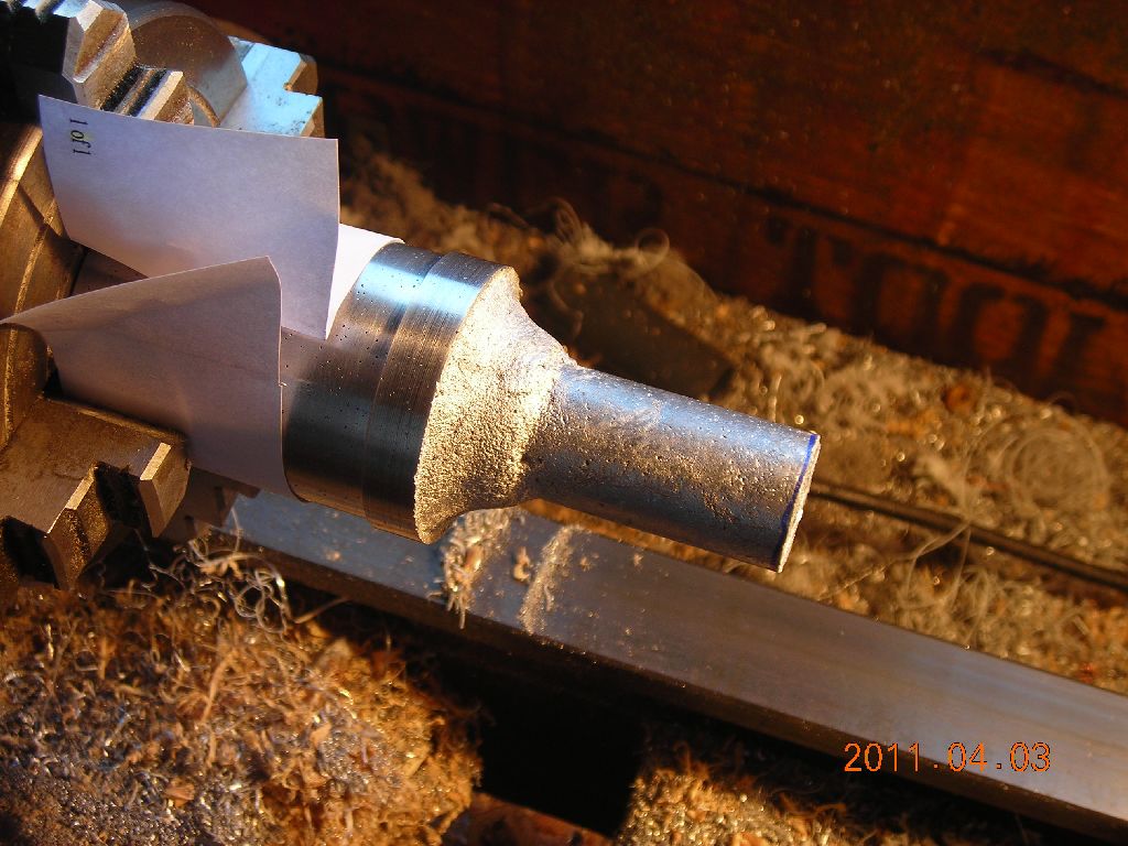
 Large diameter turned first |
 |
 |
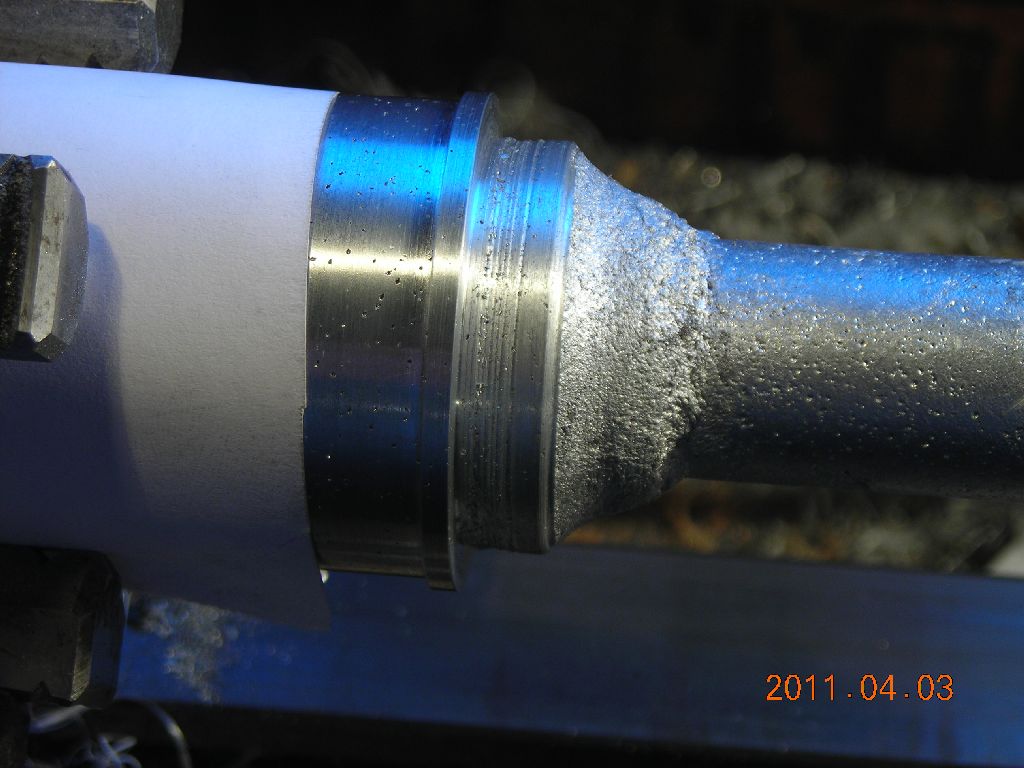 Working on the radius corner |
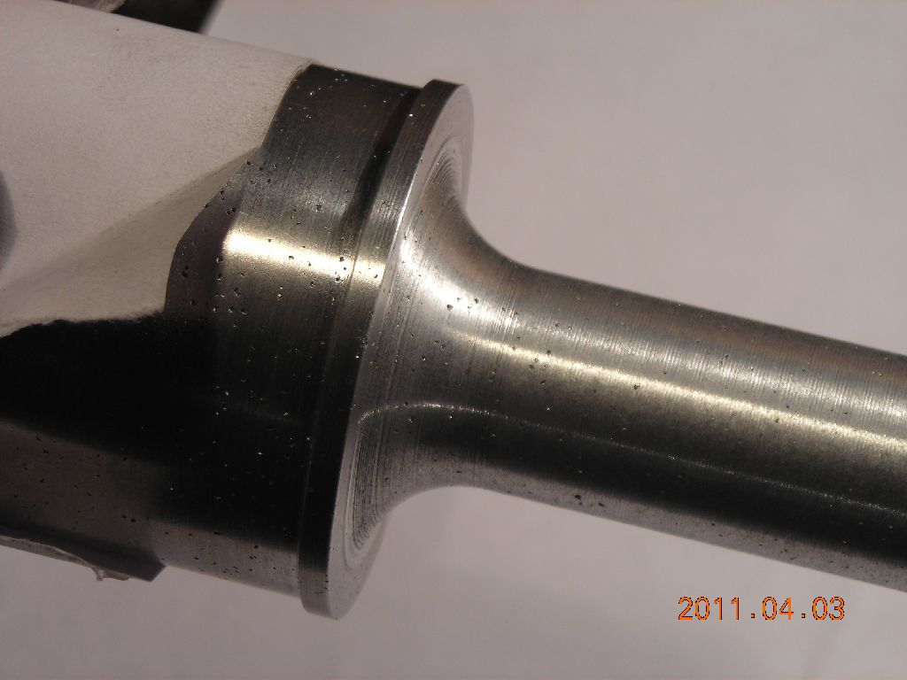 Roughed out - about 200 manual cuts to pre-calculated depths |
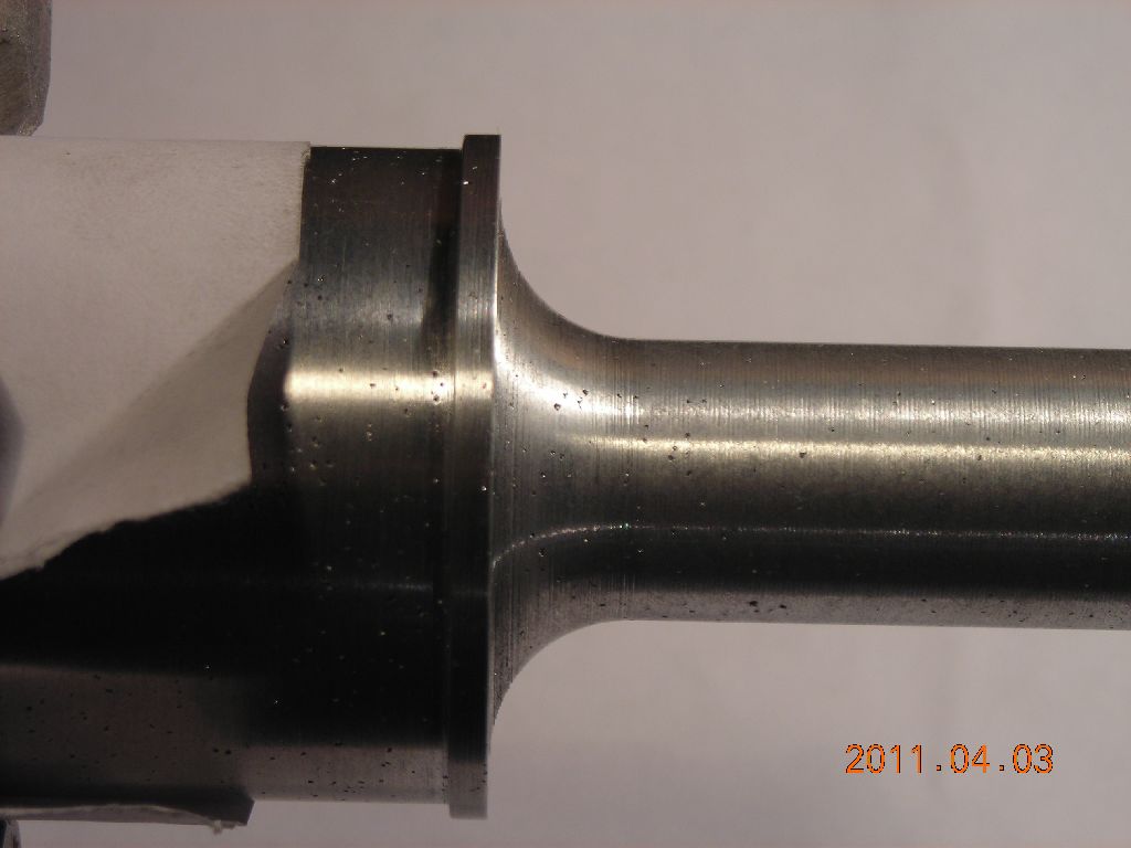 |
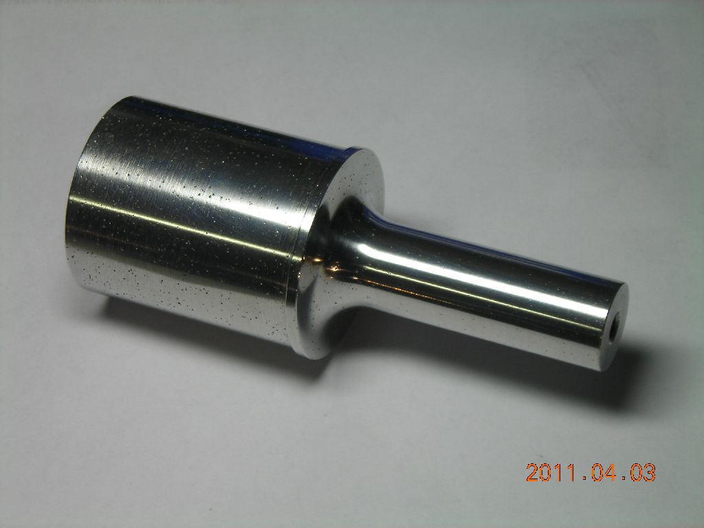
 Polished up with Autosol |
 This is over-length; will be machined down later. |
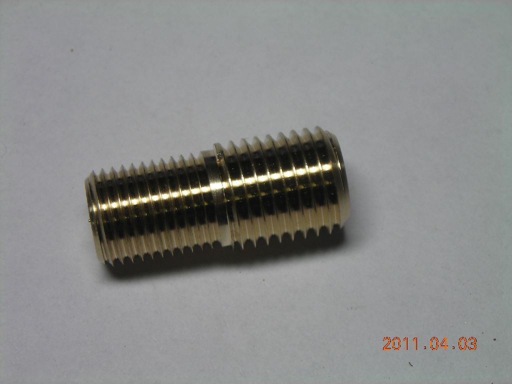 Coupling stud between horn and transducer |
 Mounting bracket casting |
 In lathe for turning down |
 Finished bracket |
 |
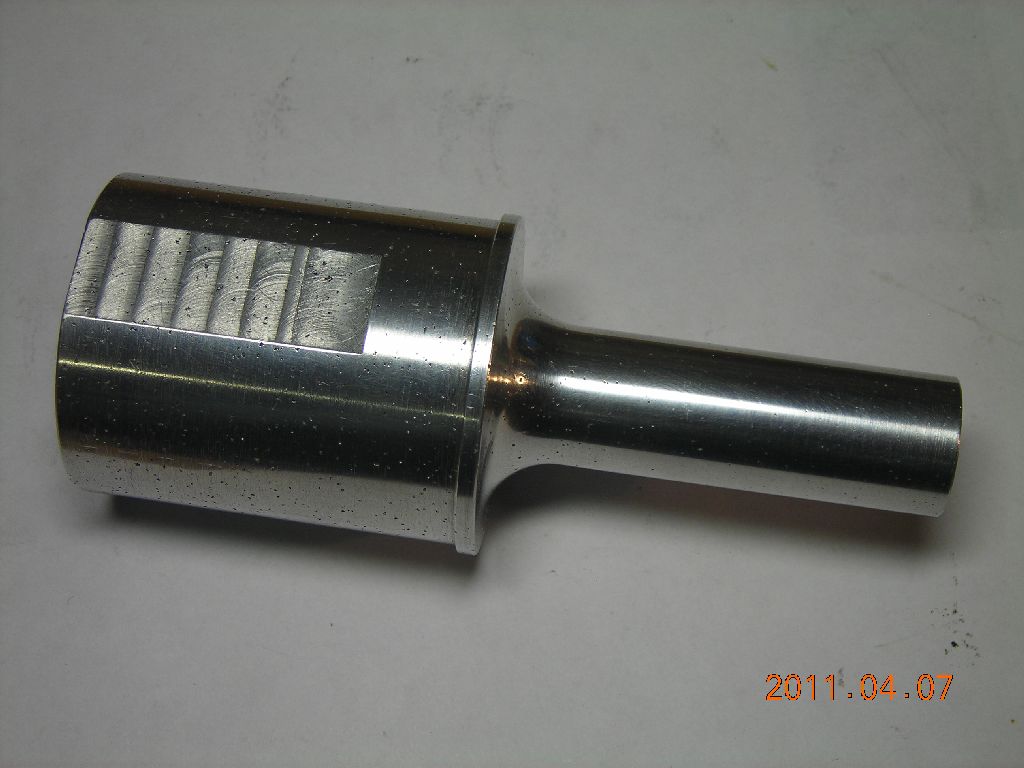 Couple of flats machined on horn for grip |
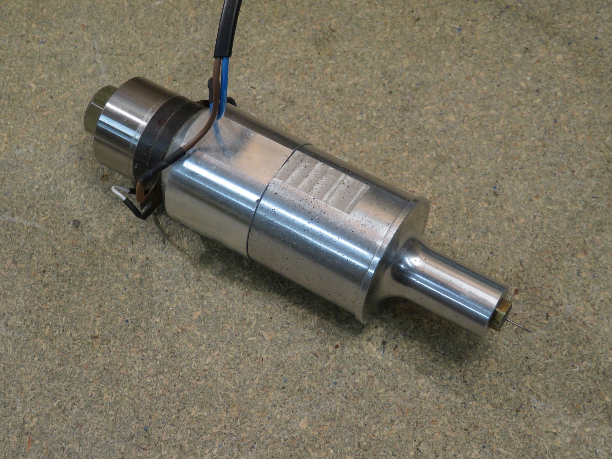
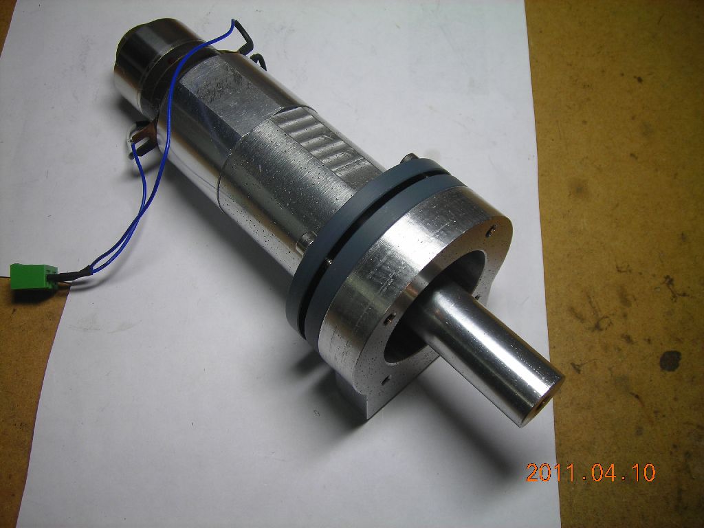 Horn+transducer mounted on bracket |
 Closeup of mounting flanges |
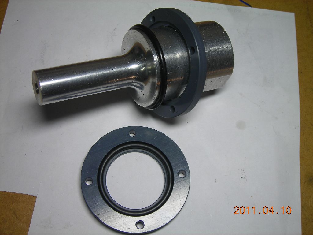 Two O-rings are placed either side of the ridge on the horn, and these are held between the two plastic rings. |
Once the horn was cast and turned to shape, I next tuned it by machining material off both ends symmetrically and measuring the frequency response at each length. This was a little bit tricky, because I couldn't decide what sort of thing I wanted to have on the end of the horn as I was tuning it - a sonication probe, a knife, drilling tip etc. I eventually tuned the horn to about 28kHz with a drilltip attached (this is simply a piece of 0.7mm steel wire soldered into an M6 brass screw). For a sonication probe, I attached another ½-wavelength piece of 13mm aluminium to the end of the horn and machined this extra piece of aluminium to tune the overall system to 28kHz again.
Shown below are the frequency responses during tuning of the horn, and of the entire system with a 0.7mm drilltip attached. The responses measured in the first graph were with an aluminium tip on the end of the horn, not the drilltip - I hadn't made up my mind what I wanted at that stage. The resonant frequency with the drilltip is very close to that of the bare transducer.
 Impedances during tuning process |
 Impedance with drill tip |
At this stage, I was satisfied I now had a transducer+horn system which would resonate at the correct frequency. My next step was to built a driver circuit.
I mentioned above that, at resonance, the ultrasonic transducer appears electrically like a series LC resonant circuit. This means that it can easily be driven by a voltage-fed squarewave inverter. I used a little half-bridge inverter driven from an adjustable 0-170V DC supply, which was obtained from a modified site transformer plus variac. Oscillation frequency is manually adjusted with a 10-turn potentiometer in the range 27-29kHz. Resonance is typically around 28kHz.
Here is a PDF of the entire driver circuit. Files are also available of the PCB layout of both the inverter board, and the oscillator board. Note (09/05/14): it was brought to my attention that the circuit in the ZIP file is actually different from that shown below. The SD pin of the IR2110 was pulled permanently to 0V, whereas I had modified my original board to include a switch to enable/disable the output. The circuit board files are now correct, and have a separate pin for SD so a switch can be connected.
The oscillator and inverter are pretty standard so I won't go into them in too much detail. The oscillator is a 4046 VCO (IC2). IC3 provides adjustable dead-time delay for the inverter. IC4 is the gate driver, an IR2110 chip. These are great little chips, since they can drive both high-side and low-side MOSFETs. The inverter uses two 13A MOSFETs, way overkill, but they were handy. Maximum currents are only around 0.5A. A meter provides an indication of either link voltage or current, selectable with a switch. I built the whole driver inside a PC power supply case, making use of the existing cooling fan. I used two separate PCBs for the inverter and the oscillator, so I could test them individually.
I have to stress that the input power supply to this driver must be floating, to allow for safe handling of the ultrasonic transducer. I achieve this by using a site transformer as an isolation transformer.
 Testing in water with a ½" extension rod |
 Prototype of the driving circuit |
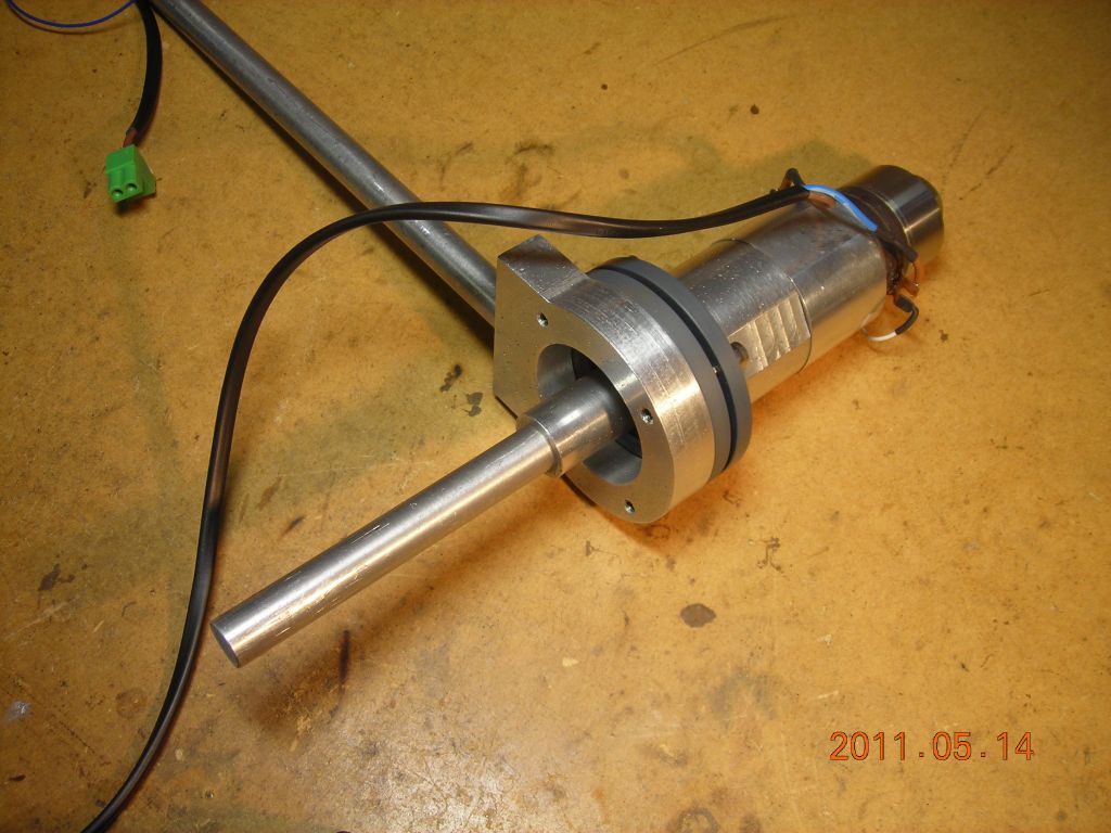 Transducer and horn mounted on bracket |
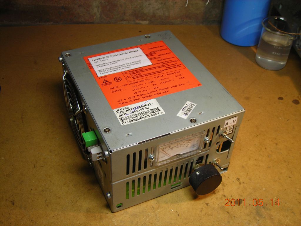 Final, boxed supply |
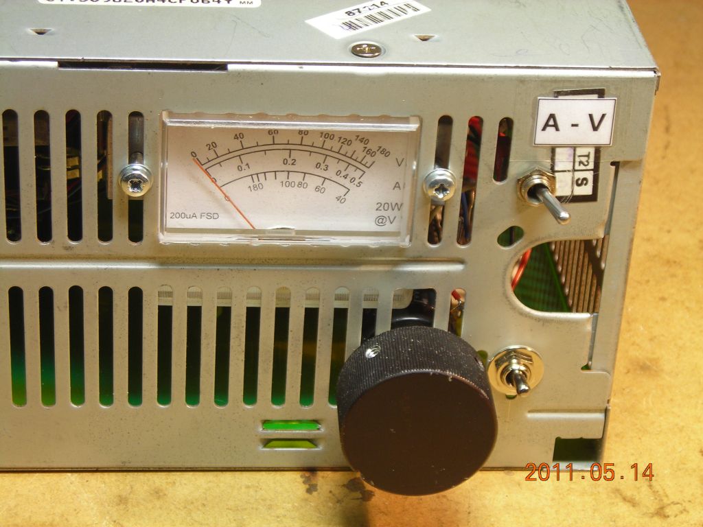 Controls - meter, scale select, and tuning adjustment. Note non-linear meter scale! |
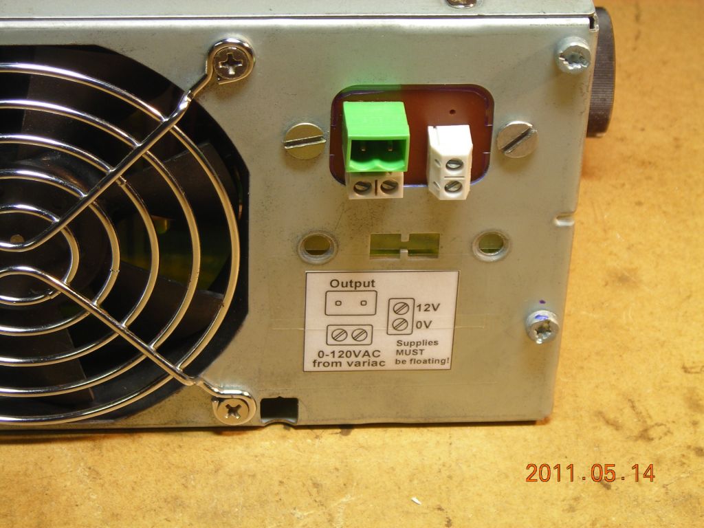 Power connections |
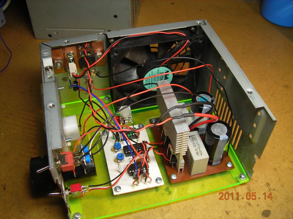 Innards of supply |
 Oscillator & gate driver PCB |
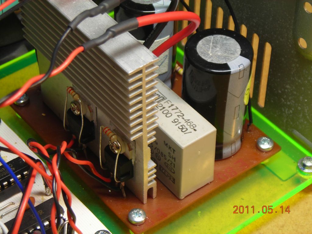 Inverter PCB |
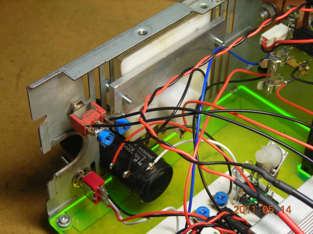 Rear of controls |
 Power connections |
 Completed driver running |
Here's a quick video showing the tuning process. Resonance is very sharp, maybe only a few 100Hz wide, but the multiturn pot provides fine enough adjustment.
Next, here's a video showing cavitation in water. This is using a ½" aluminium bar as an extension, attached to the main horn. Input power is about 50W. The cavitation is powerful enough that it wears away the end of the tip after only a few mintues!
Here's the effect on fresh lemonade, showing the degassing effect of ultrasound. Also be sure to check out TheBackyardScientist's video as well!
Lastly, check out the page on ultrasonic drilling, which is what originally started me off on all this.
Over the past few years, I keep getting inquiries from people asking about how to measure the resonant frequency of these transducers, how to design horns, tune the length etc. I decided it was time to do a video about the entire process - hopefully I've covered everything relevant. If you check the YouTube description, I've put time links to each individual section of the video.
Here's some more photos of the transducer and horn I took when filming the video.
 |
 |
 |
 |
 |
Although the horn obviously works, and provides enough power to, for example, cause cavitation in liquids, I've never been sure of the actual tip displacement and how it compares with a commercial unit. From what I can find (e.g. this guide for ultrasonic welding), the peak-to-peak displacement is on the order of tens of microns, so I'd need something pretty sensitive to measure it.
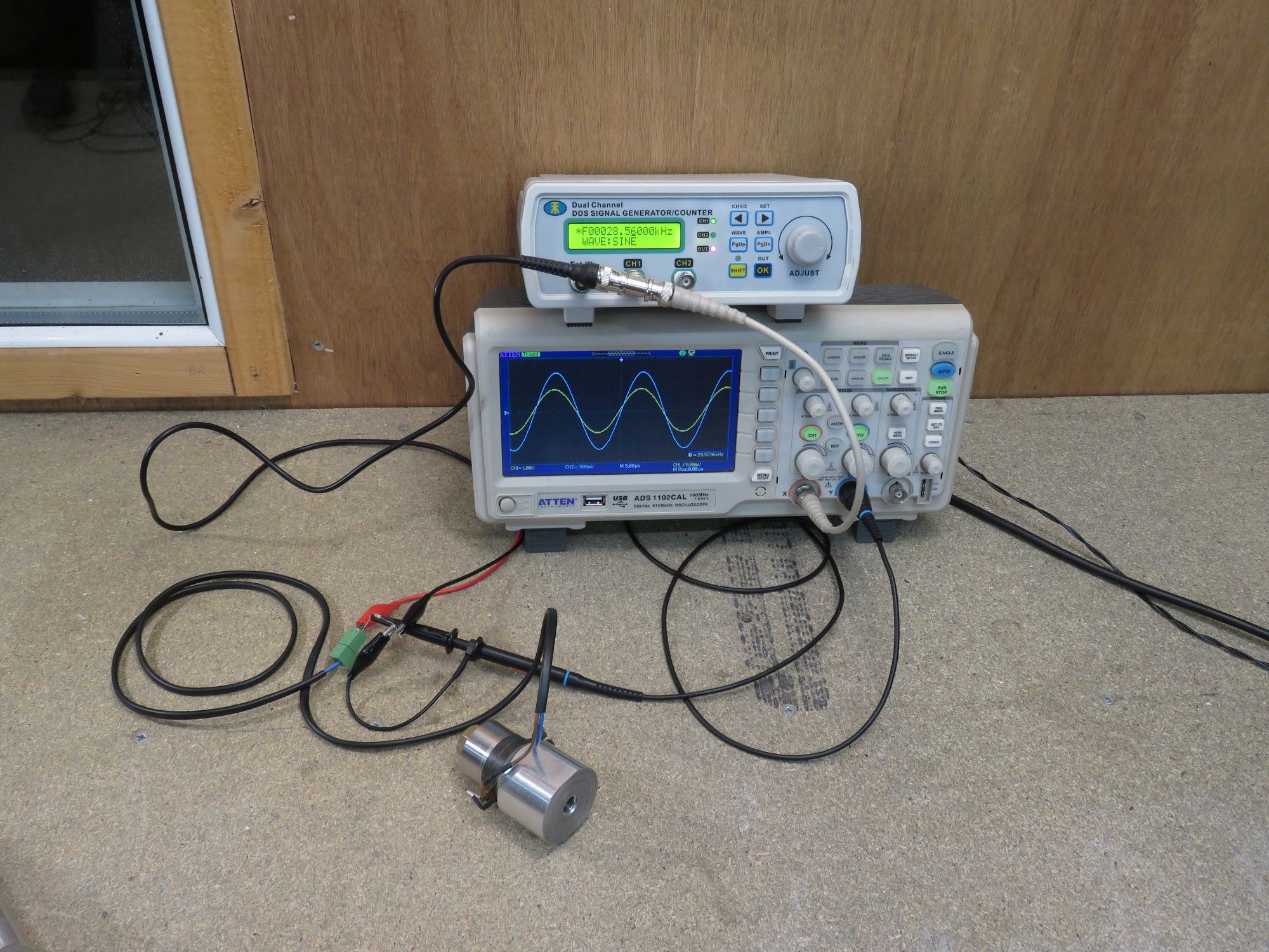
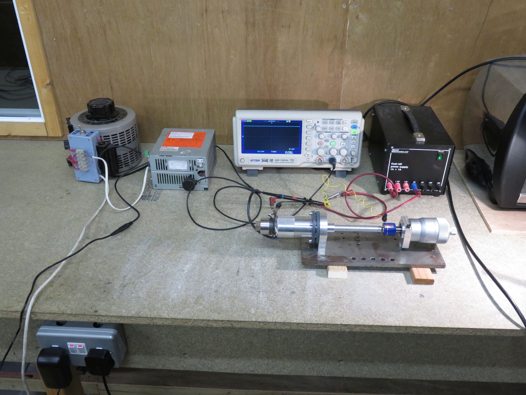
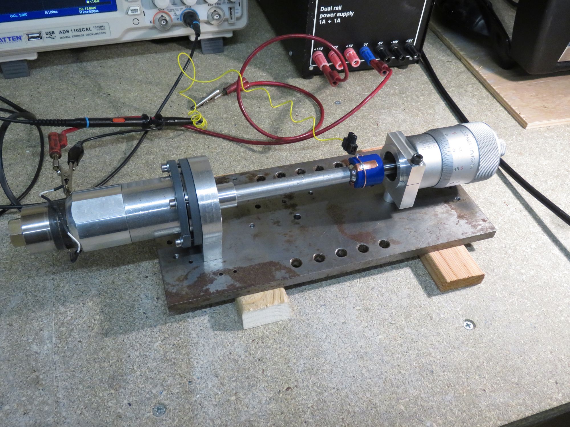
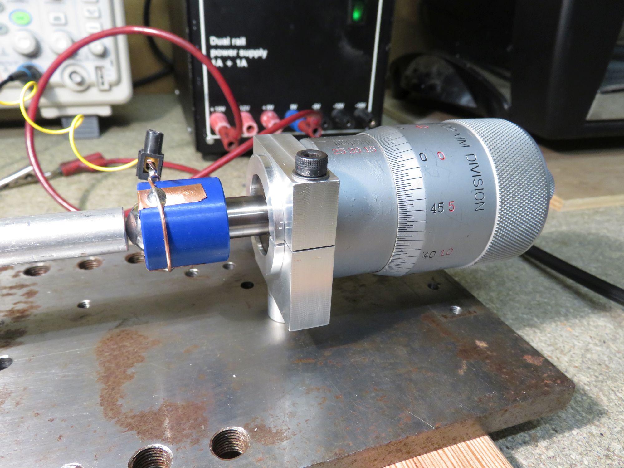
I have some huge Starrett 468M micrometers, which read to 2 microns, so decided to try and use one of them. My original plan was to detect the capacitance between a large steel ball and the tip of the horn, but the capacitance is so tiny, and the variation even smaller, that this was pretty impossible. Instead, I did something a bit simpler. The steel ball is mounted on the tip of the micrometer in a plastic holder to keep it insulated. The ball is biased to 15V through a 47kΩ resistor, and the tip of the horn grounded. An oscilloscope meausures the voltage on the ball - it normally sites at 15V, but drops to 0V as soon as it touches the tip of the horn.
I turned the horn on and moved the micrometer in until I could just see "dips" in the voltage, caused by the ball touching the horn at the peak of its vibration. Here's a scope shot:
I then turned the horn off and moved the micrometer in further until the ball shorted out. The distance between these two readings is half the peak-to-peak displacement. In my case, I measured a p-p displacement of 20 microns, which is at least in the right ballpark.
Here's some photos and video of the setup. It's rather satisfying to be able to measure something this small and get a reading that's sort of reasonable!
 |
 |
 |
 |
| ▲ Electronics |