| ▲ Electronics |
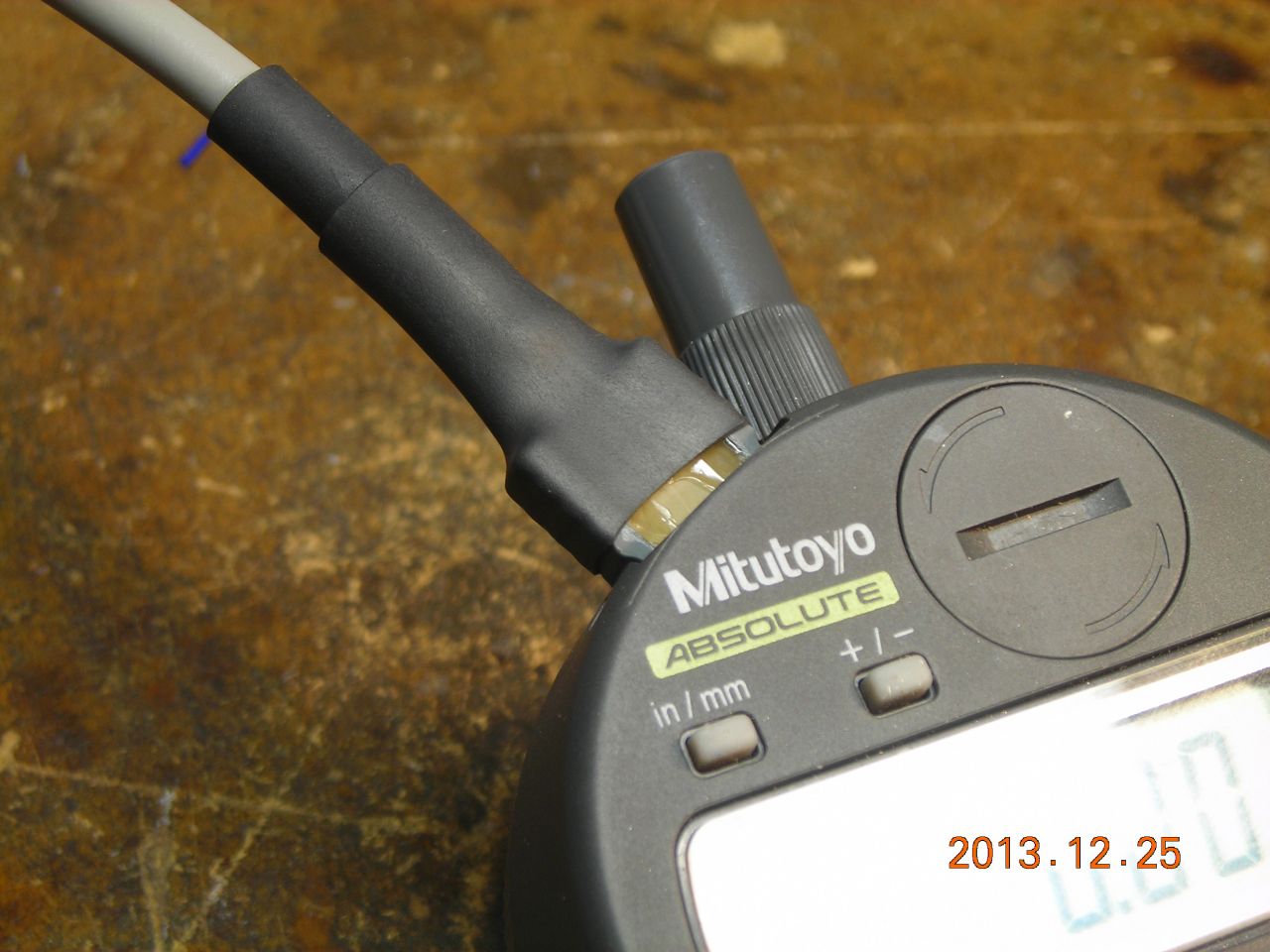
I have a Mitutoyo digital test indicator (part number 543-682) which I frequently use for setting up work in the 4-jaw chuck. However, it usually ends up in such a position that I can't easily read the display. Since all Mitutoyo devices have a digital interface port (called "SPC"), I decided to make a remote readout with an analogue display (since it's much easier to read a needle than a numeric display).
Ready-made cables are available which connect the indicator to an "official" readout unit. However, these are rather expensive (over £30) so I reckoned it would be cheaper to make my own cable. In retrospect, it would have been much simpler just to buy one! Such is the benefit of hindsight.
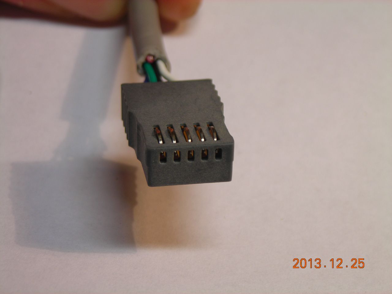
First, I measure the pitch of the contacts on the connector - 1.6mm. Try as I might, I simply could not find any sort of connector, header, card or anything that had the same pitch (my plan was to remove the contacts and make a new housing). It looks like Mitutoyo have deliberately used a non-standard pitch.
Desparate measures called for. I cannibalised the spring contacts out of a PCI card-edge riser, made a little bit of PCB to hold the contacts and milled out a housing from PVC flat sheet to hold the PCB. There are little holes in the housing through which the tips of the spring contacts protrude. Getting the exact dimensions of the outside was very tricky, and I went through 3 or 4 until I had one that fitted just nicely. Unfortuntely I broke off the retaining clip inside the indicator's socket (it engages the two small protrusions on the connector plug) because I made the protrusions too big. However, it still works fine, just the plug isn't as tight as it could be.
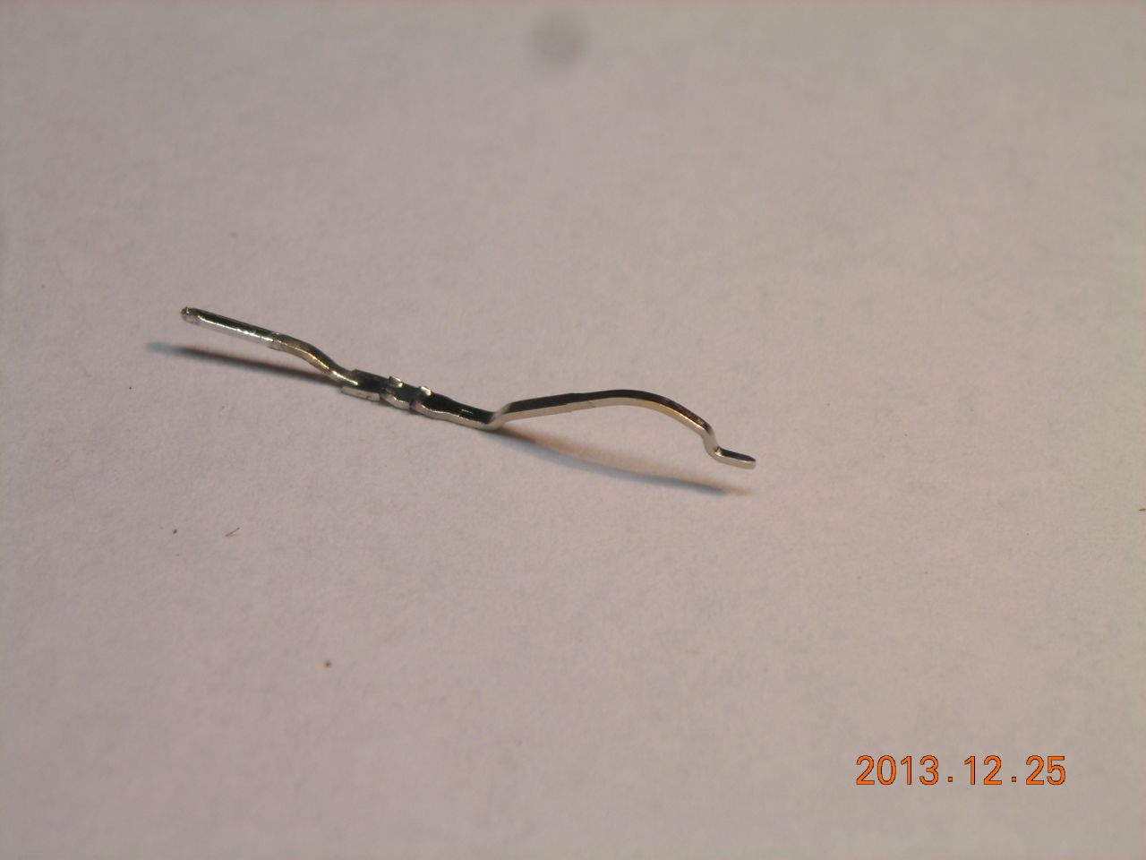
I scanned in one of the spring contacts and drew around it so I could put it into my CAD program and design the rest of the plug housing around it. I also had to make a small grooving milling cutter to form the groove which holds the PCB in the plug housing.
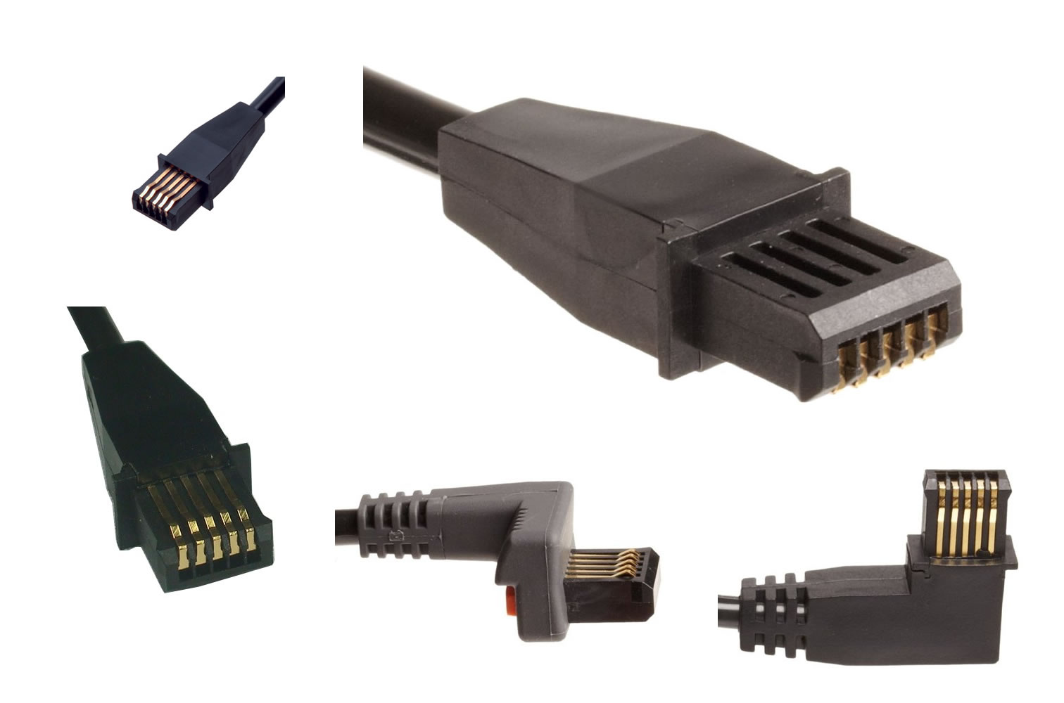
Here's some photos of a "proper" connector (taken from various places on the web):
Here's photos of the construction of my connector:
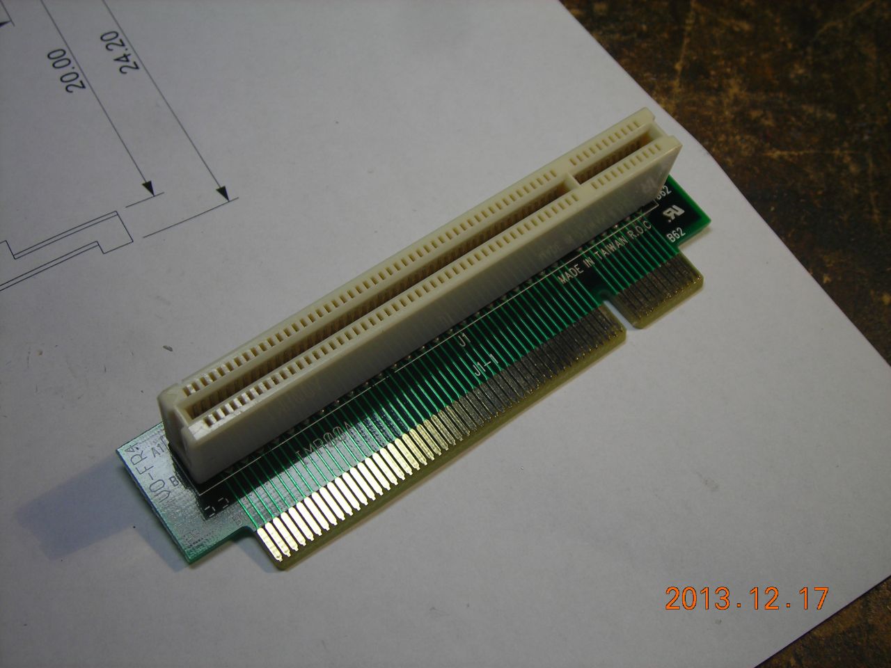 PCI riser (from EBay) |
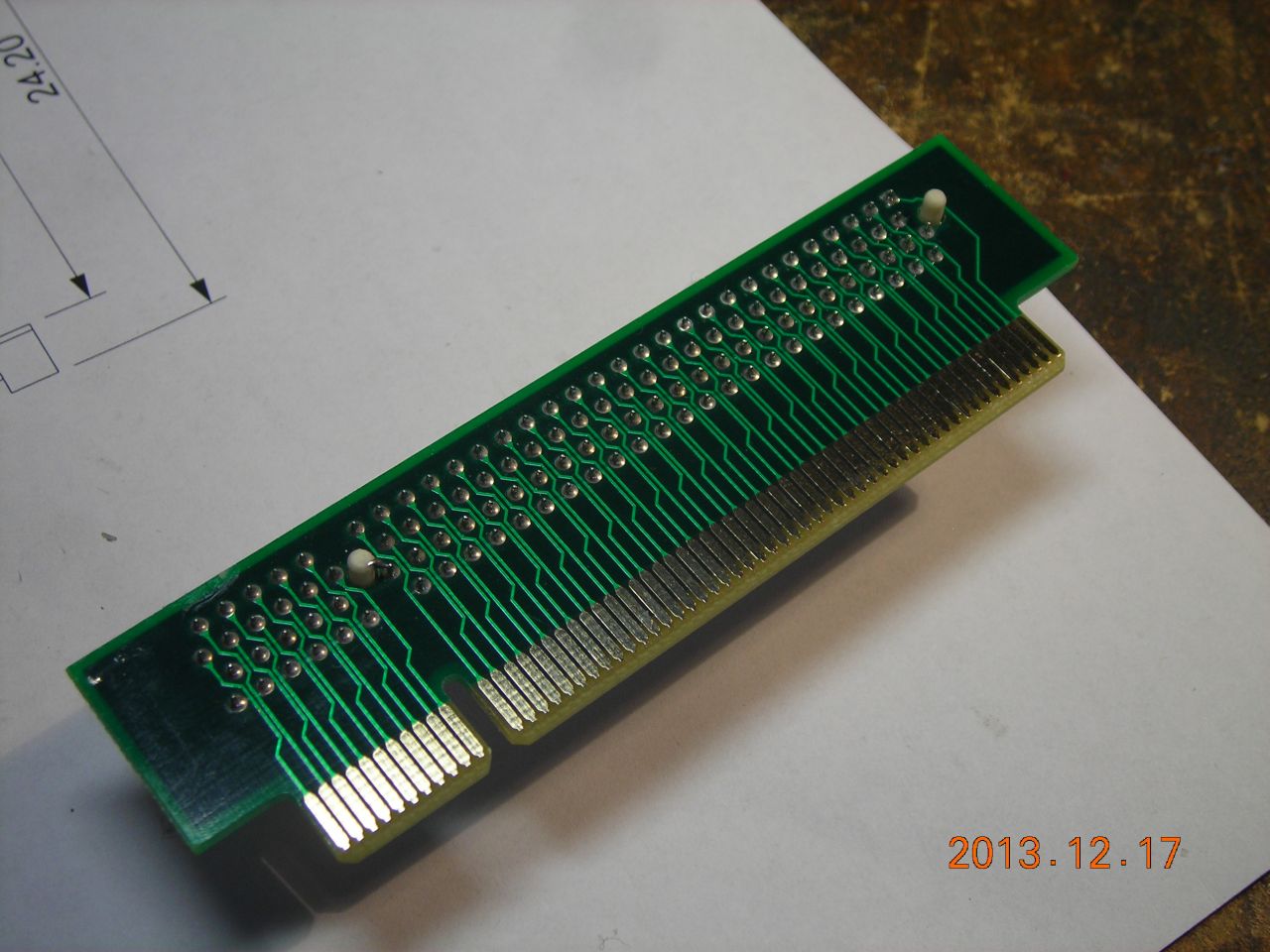 |
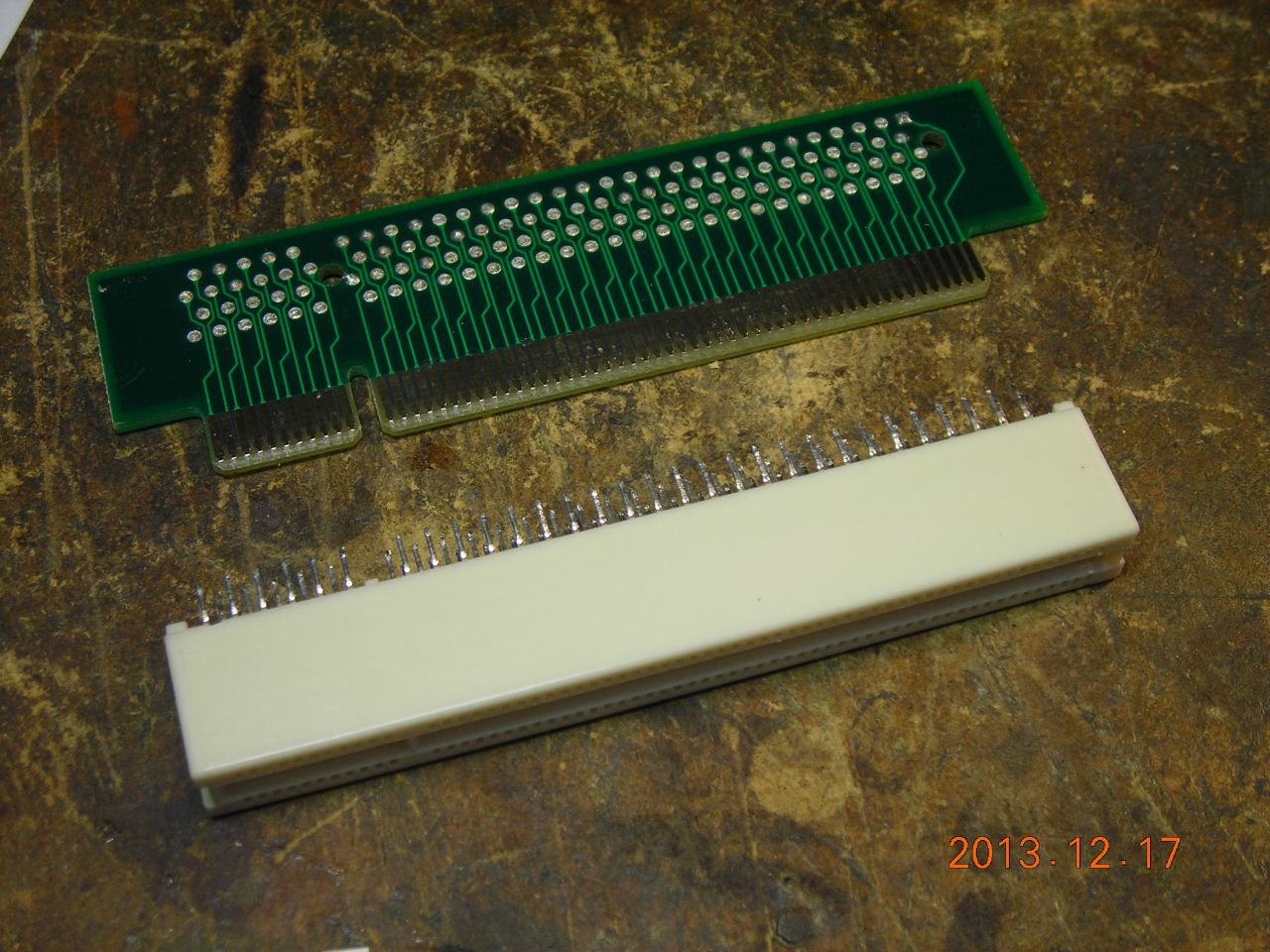 Connector removed with hot-air gun |
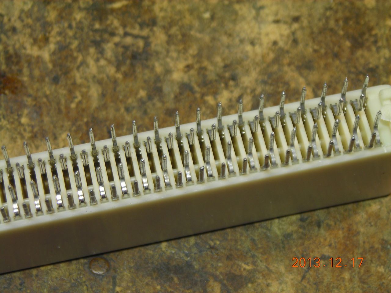 |
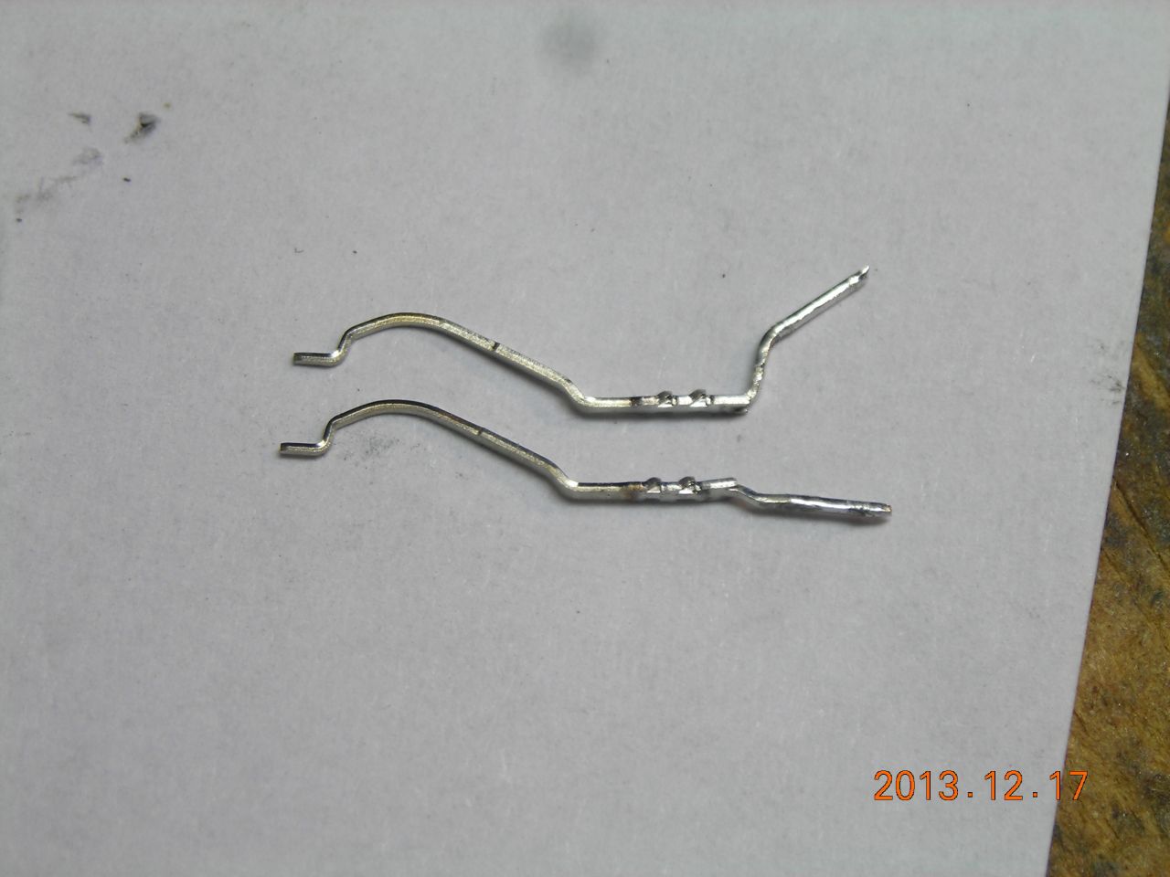 Some of the contacts pulled out |
 |
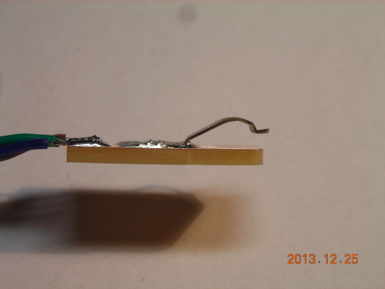
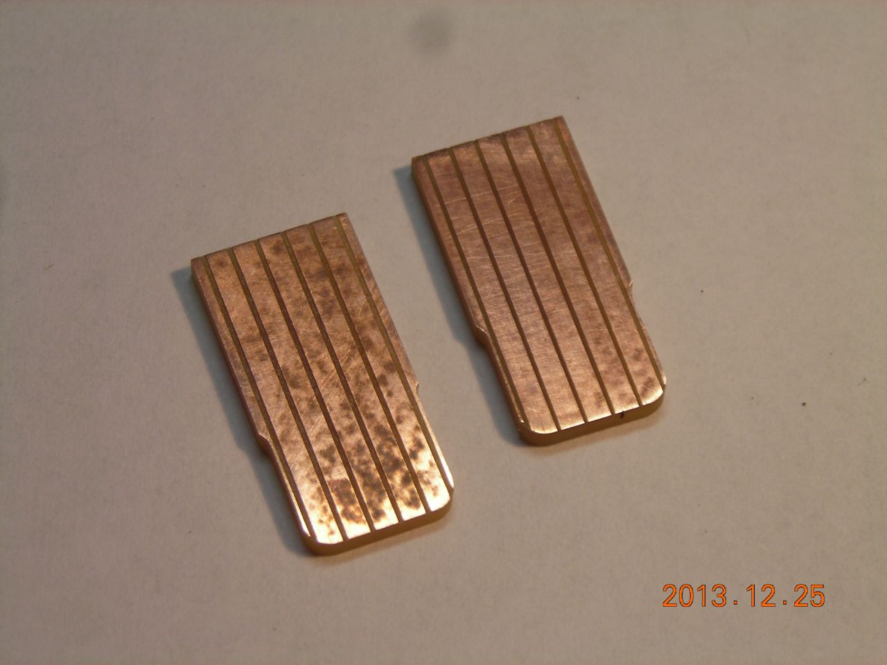 PCB to hold the contacts |
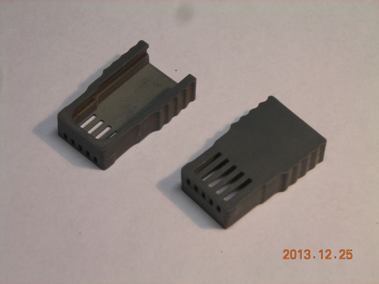 Housing |
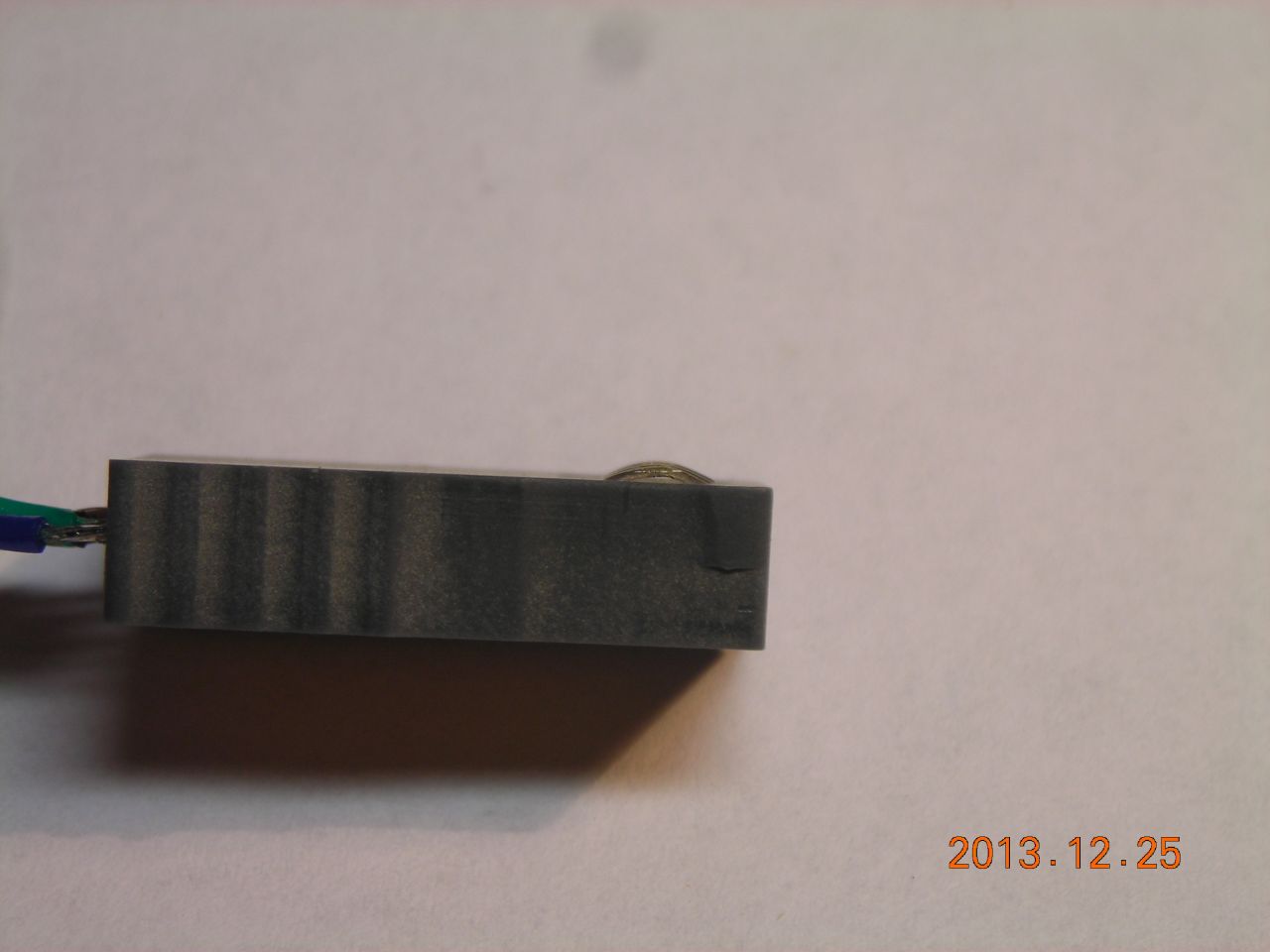
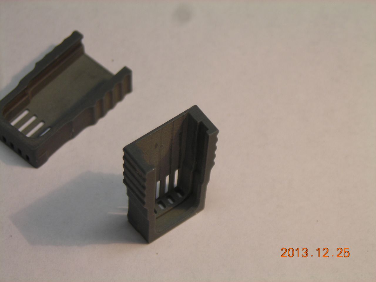 Note the slot to hold the PCB |
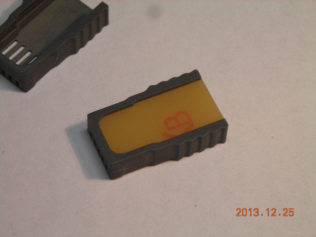 PCB inserted |
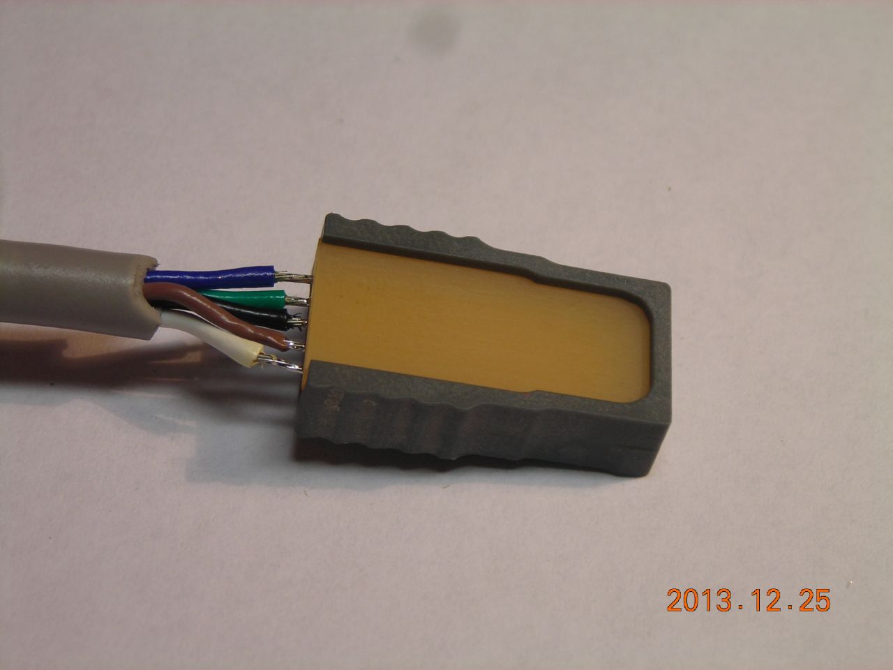
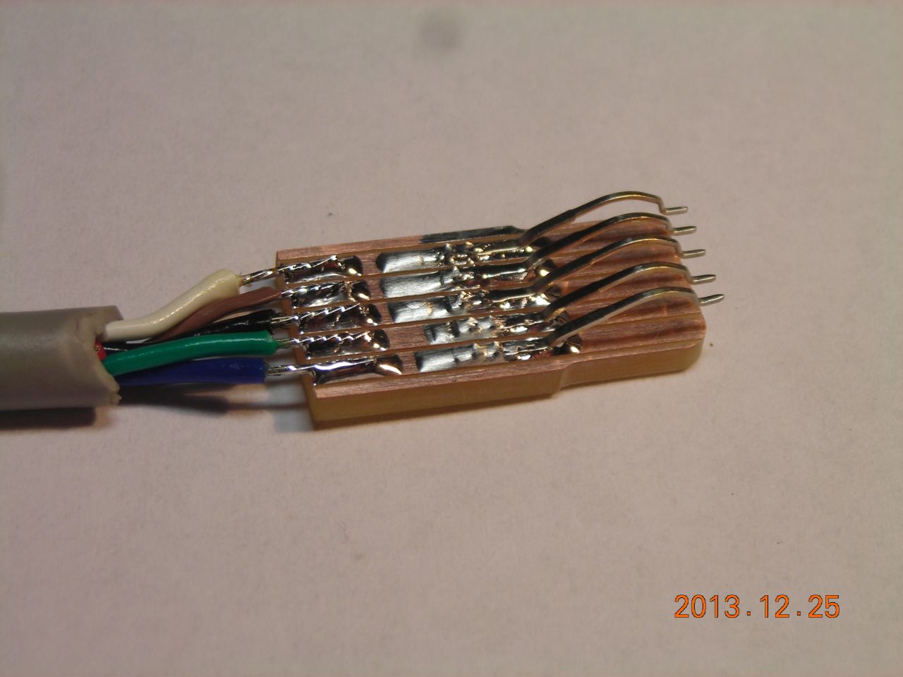 Wires attached |
 |
 Inside housing |
 |
 |
 |
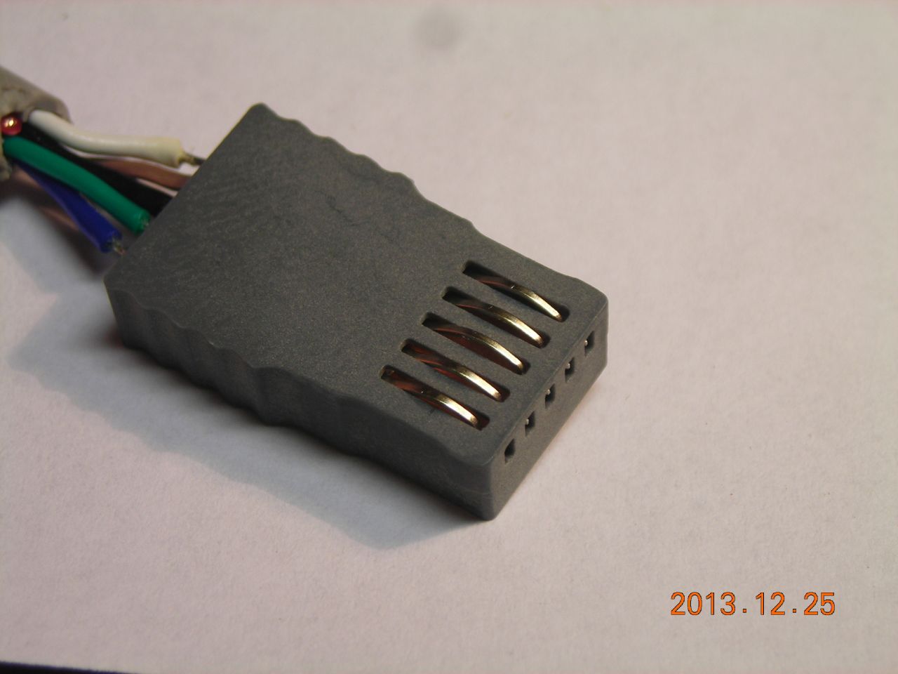
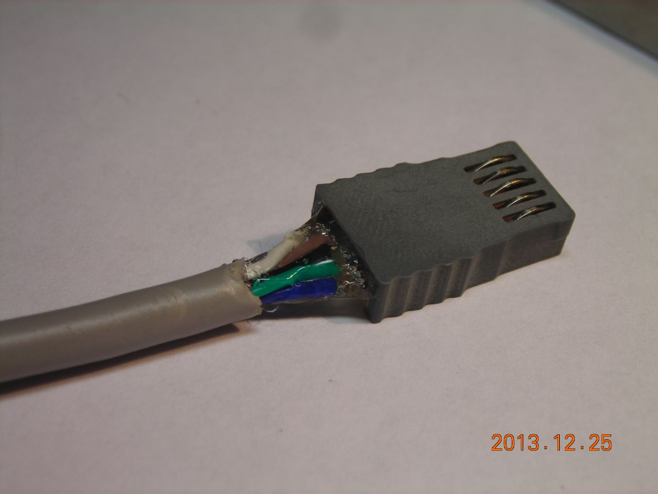 Plenty of hot-melt glue for strain relief |
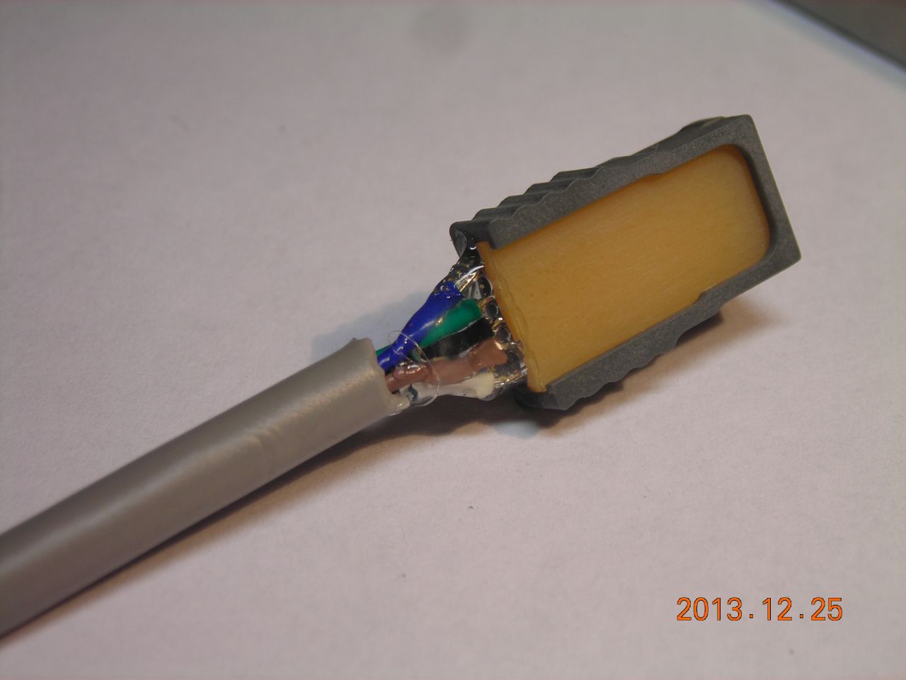 |
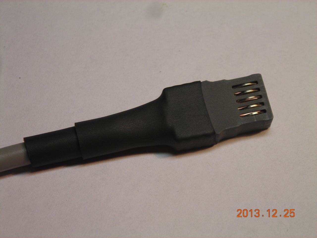 Several layers of heatshrink to finish off |
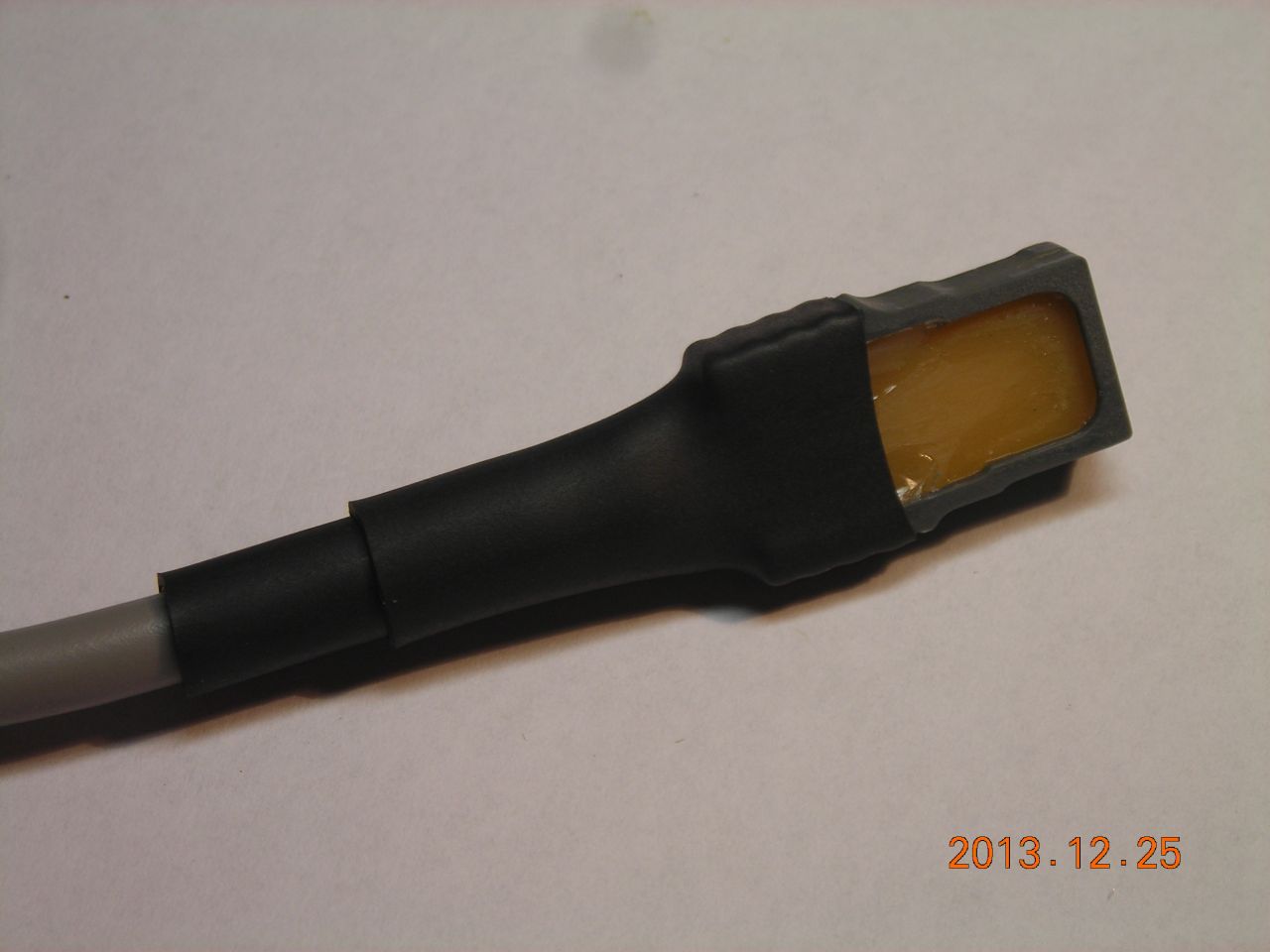 |
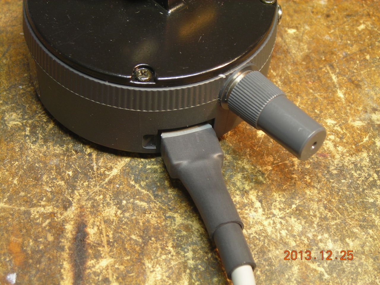
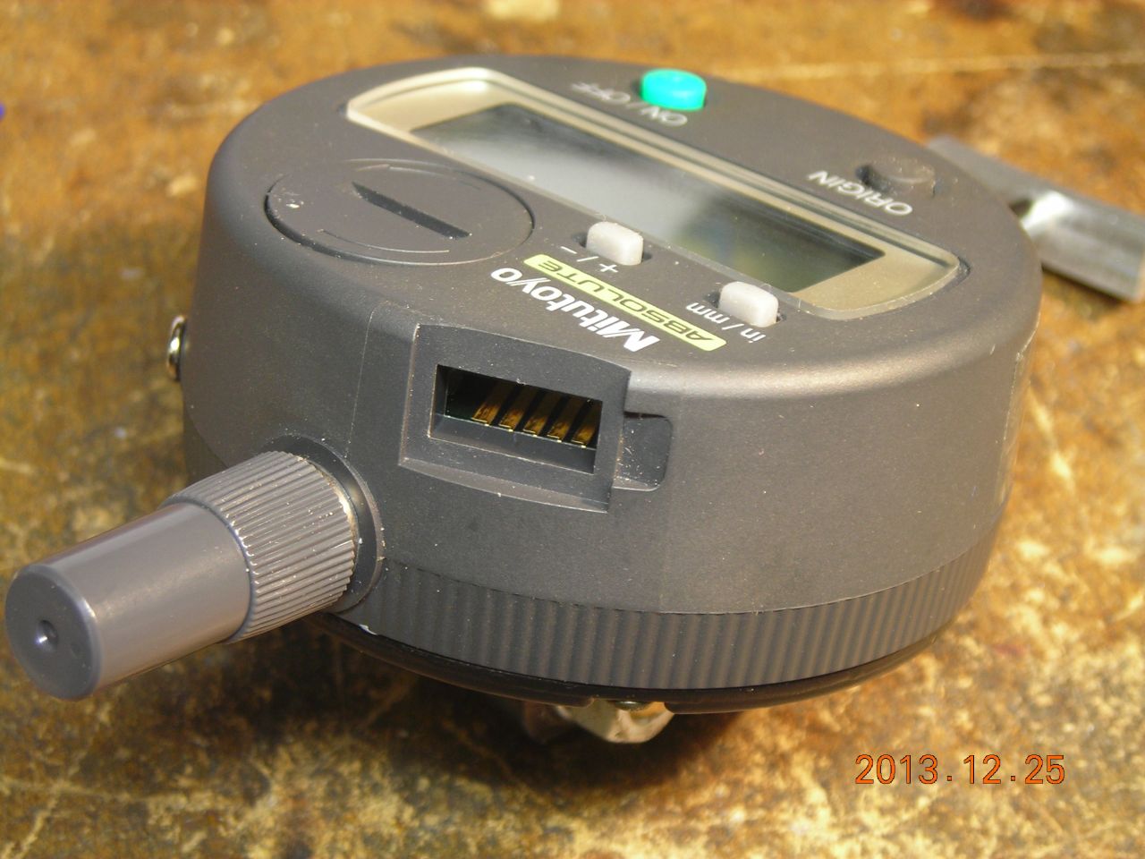 Indicator socket |
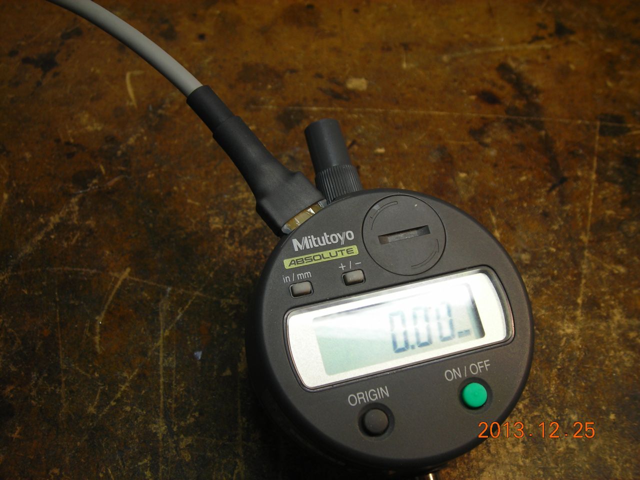 It fits! |
 |
 |
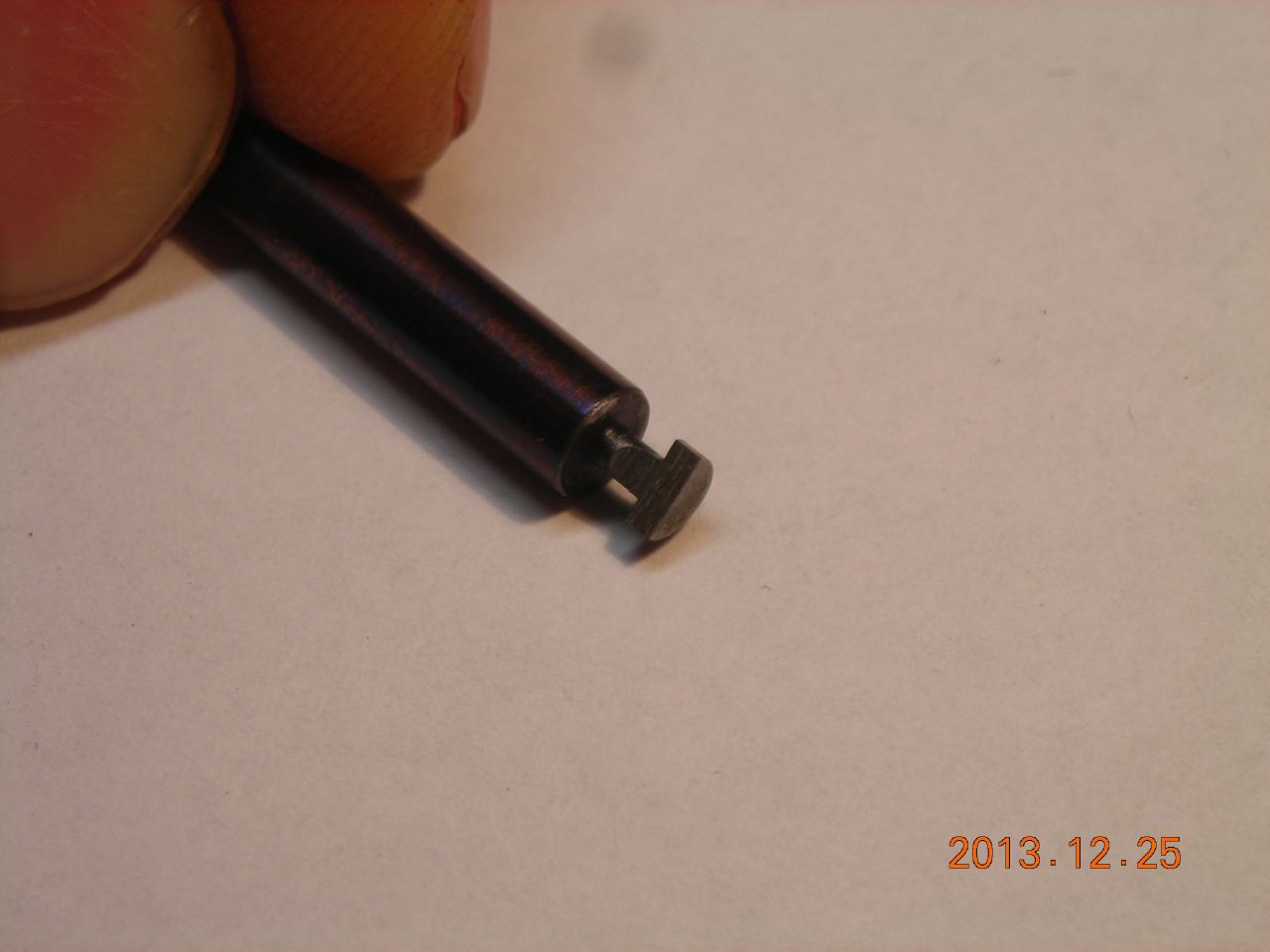 Undercutting tool for the PCB groove |
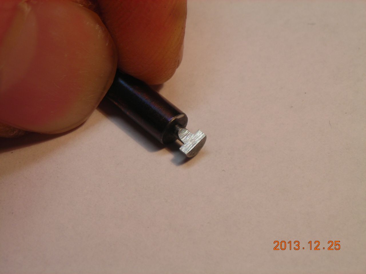 |
Here's a scan of the instructions for my gauge:
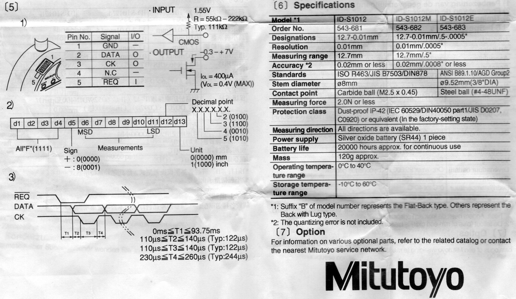
The interface uses open-collector signalling. There is a request input (to the gauge) which, when pulled low, initiates the transfer of a reading. Data is then output on the clock and data lines (these are both open-collector outputs from the gauge) and can be received by an external circuit. There are a total of 13 data bytes. Some bytes are used to indicate the sign, decimal point position, and units (mm or inch). There are various different interface circuits going around on the web (for example, see http://www.green-trust.org/digimatic/ and http://www.labviewforum.de/attachment.php?aid=21297).
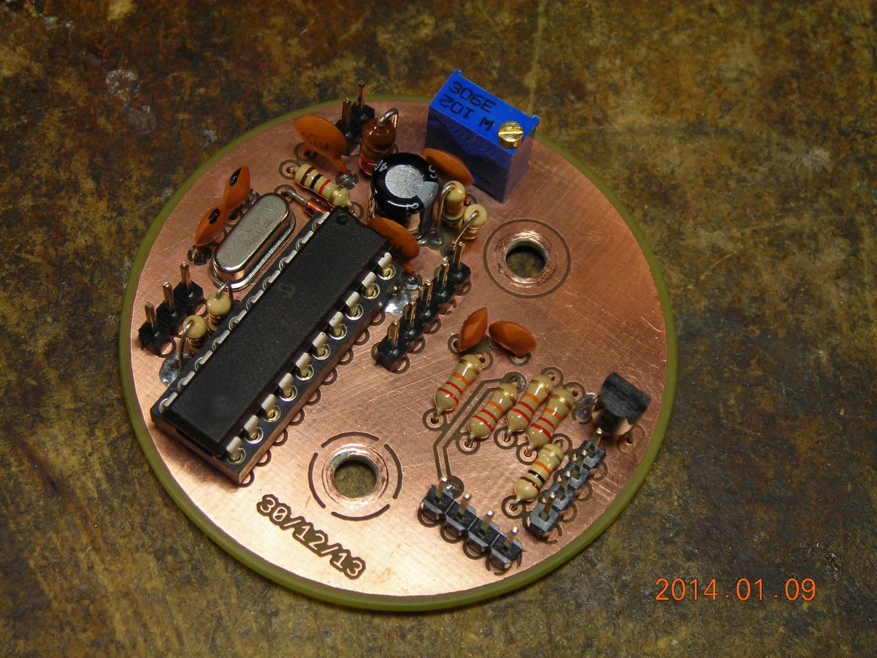
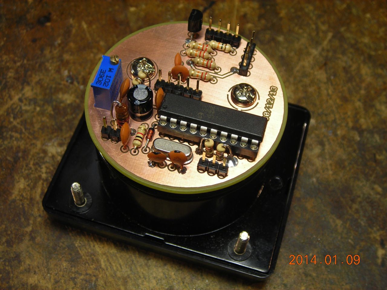
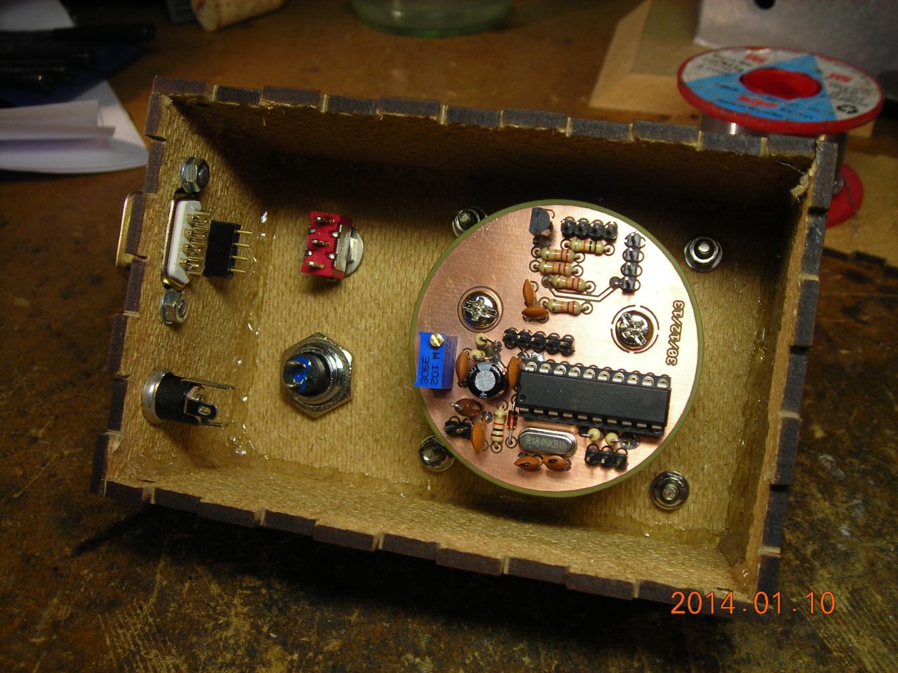
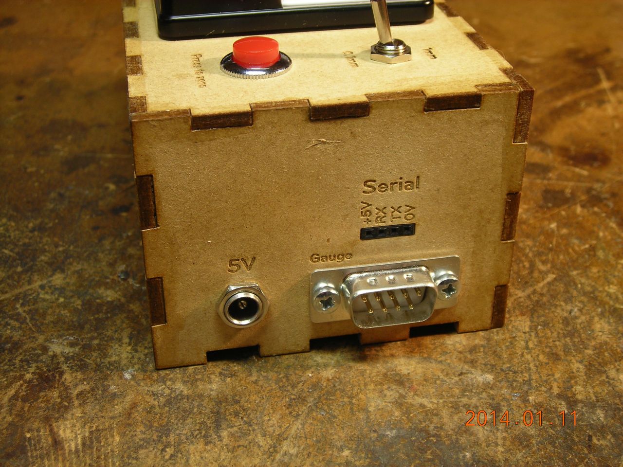
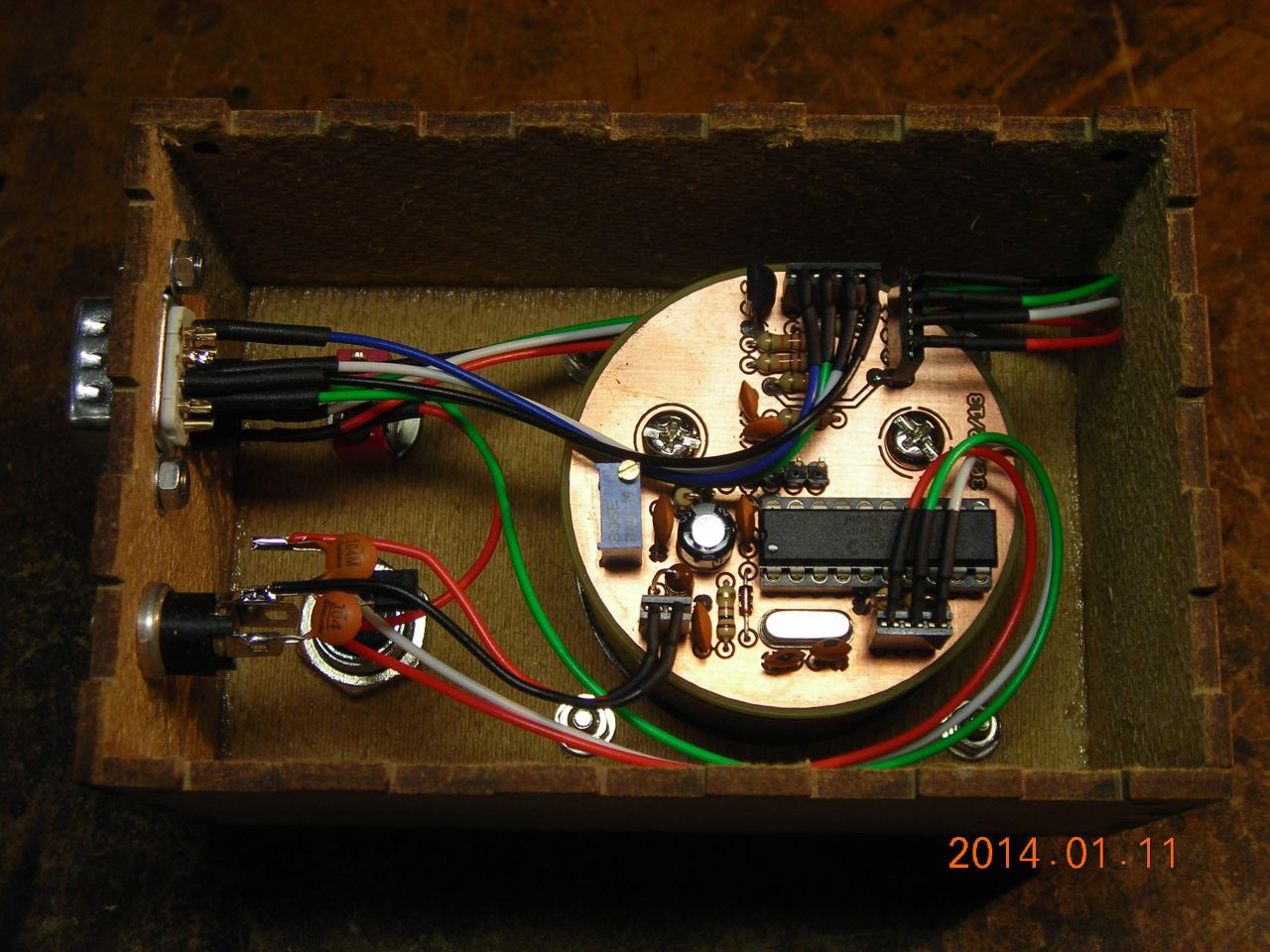
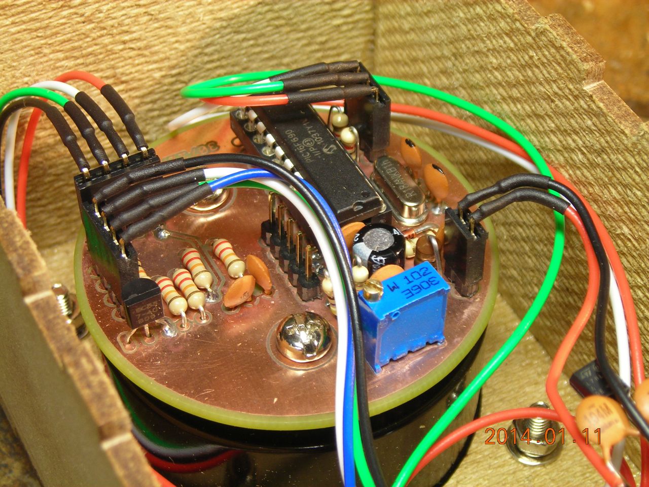
Here is the complete circuit I ended up designing. The gauge interface is based on that in the second of the two links above. A PIC micro reads a value from the gauge every 100ms or so. It compares this with a zero value, which can be set by the user by pressing a button on the readout unit, and then displays the difference on an analogue panel meter by using the PWM output. I also chucked in an RS232 serial port for good measure, so data can be output to a computer. A toggle switch allows the displayed range to be adjusted. The range and zero buttons are connected to JP4 and pull the pins to 5V.
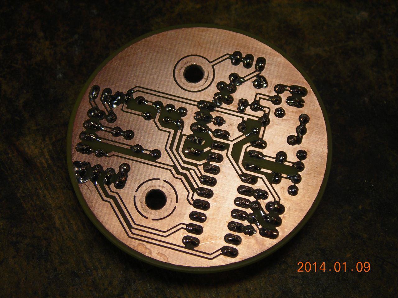
You can download a ZIP containing PCB files here. The board is design to fit on the back of the panel meter - Rapid Electronics http://www.rapidonline.com/Electrical-Power/100ua-Moving-Coil-Panel-Meter-48-0305.
Here's a ZIP with the PIC code. There's a hex file as well if you just want to burn it directly. The code is for MikroC but should be easily adapted to other compilers.
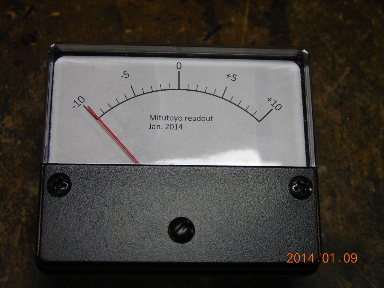
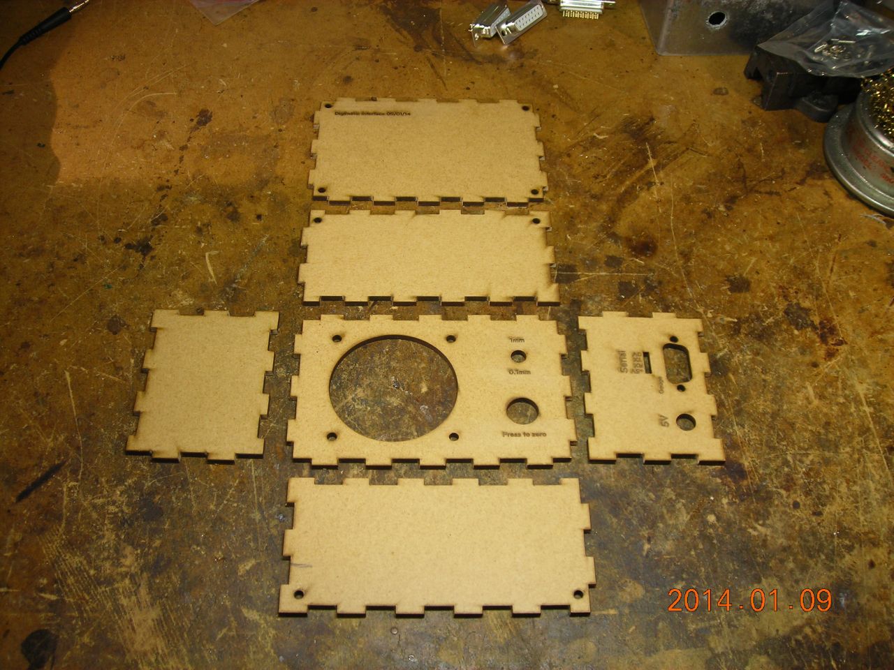
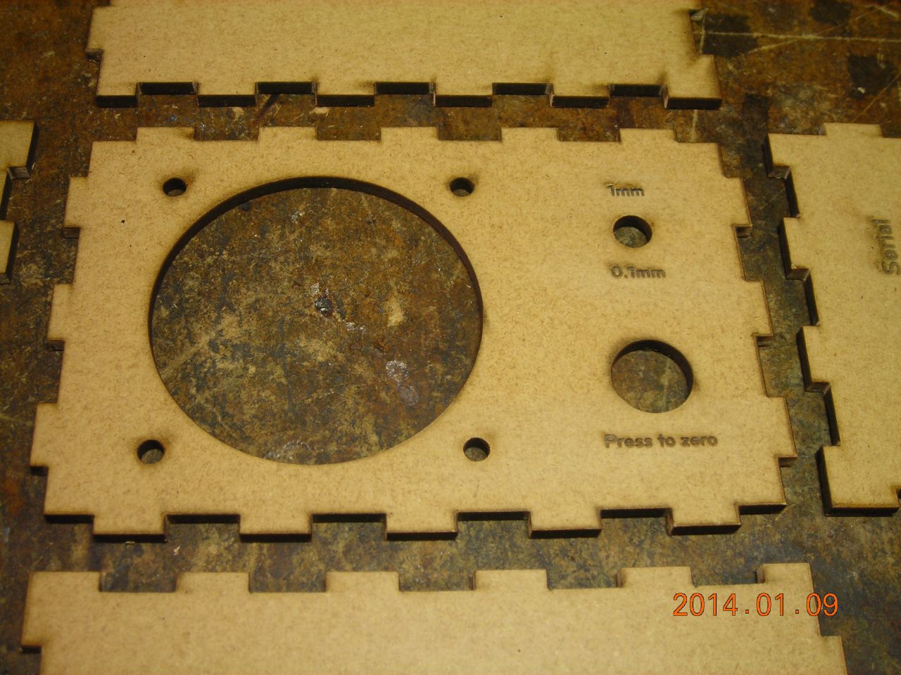
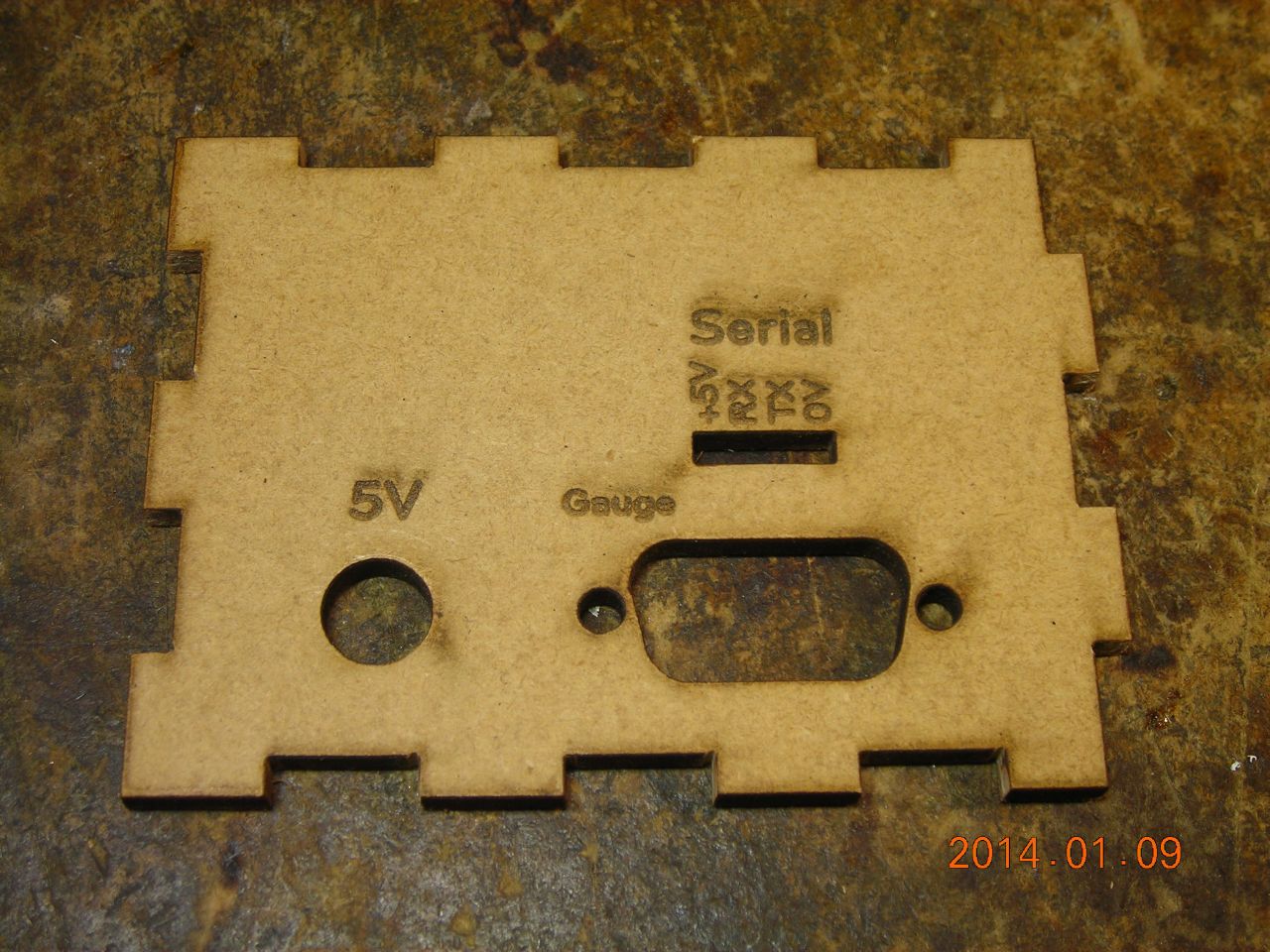
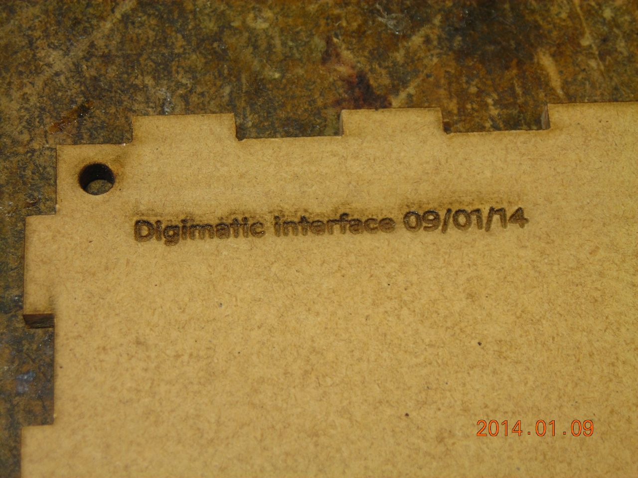
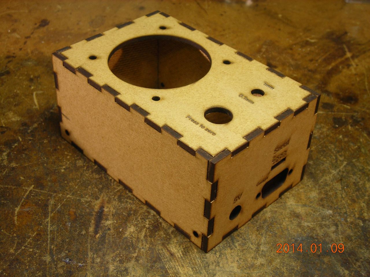
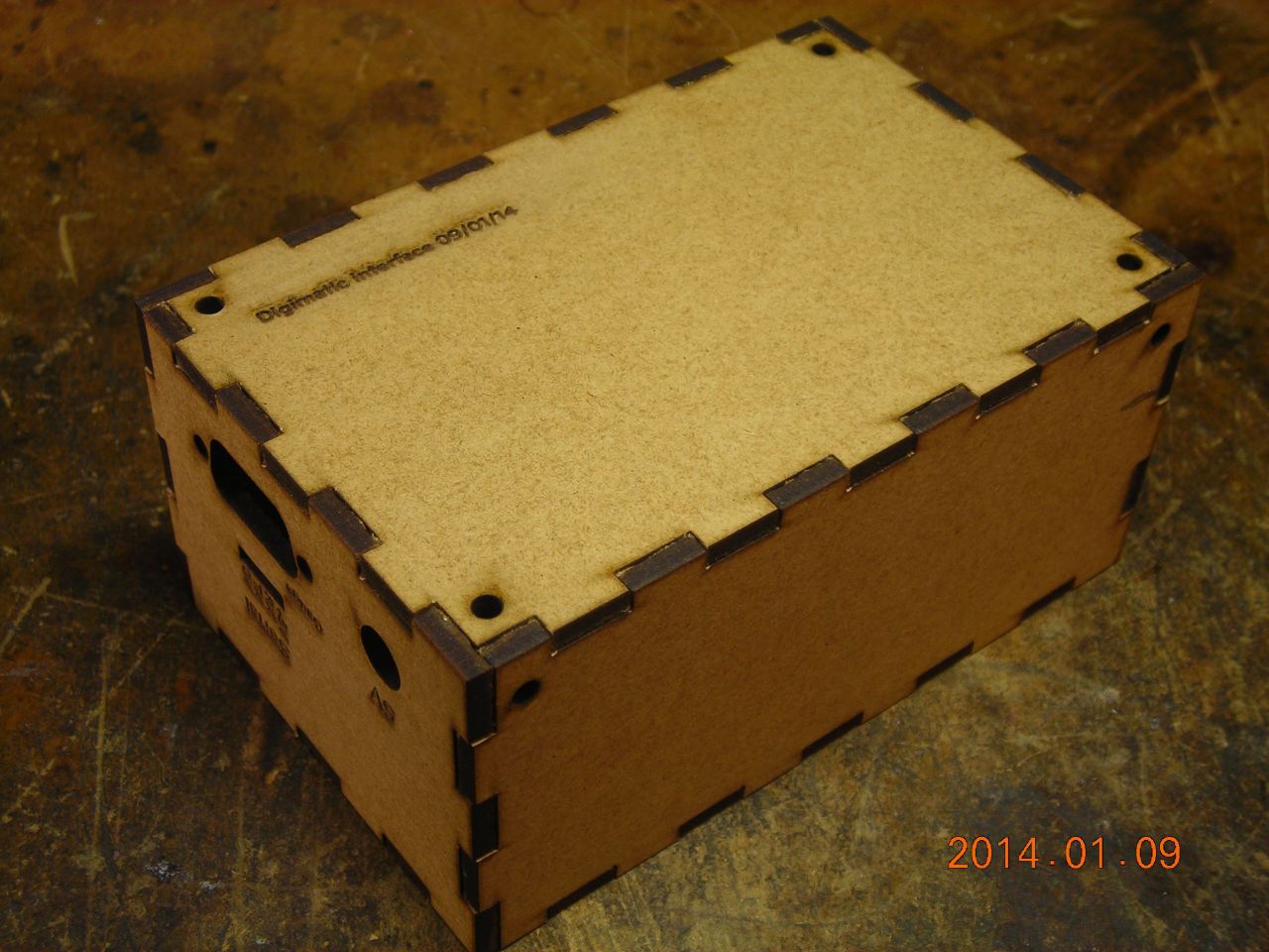
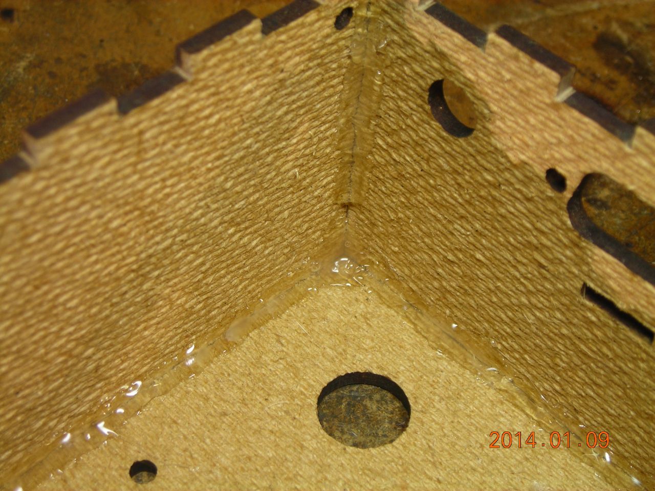
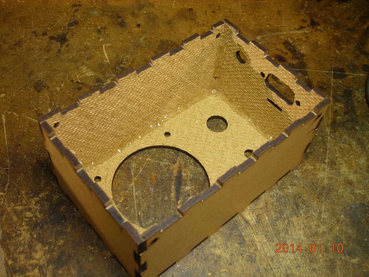
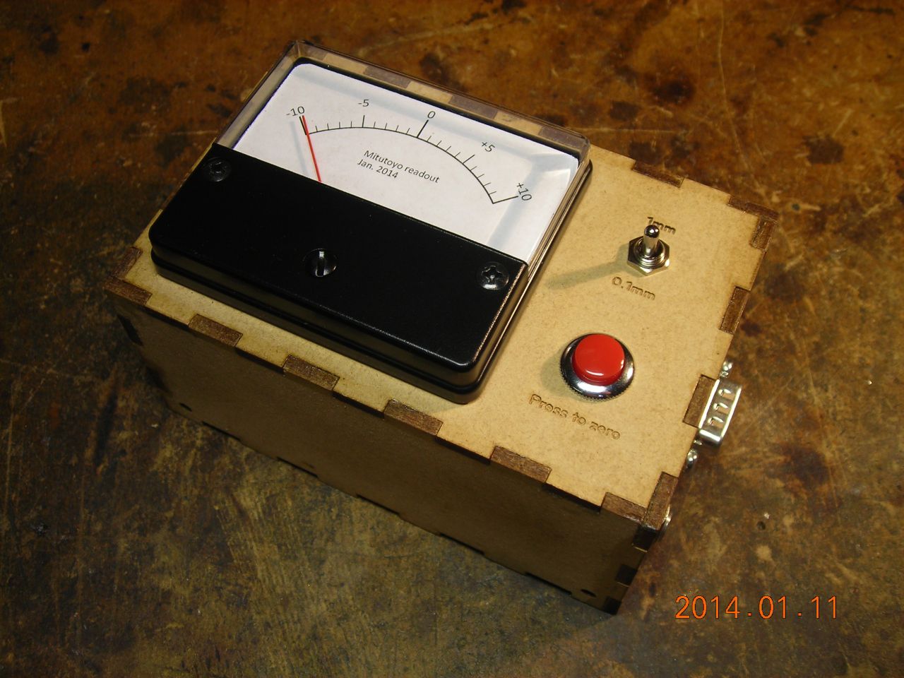
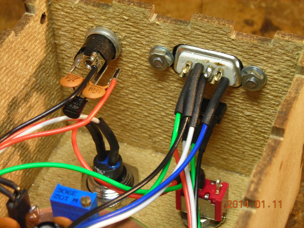
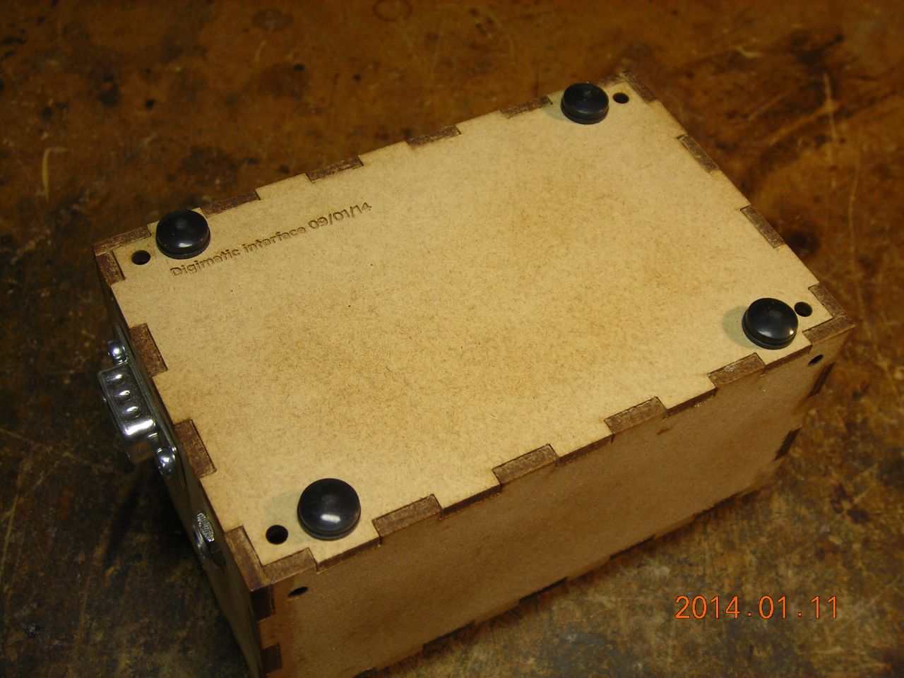
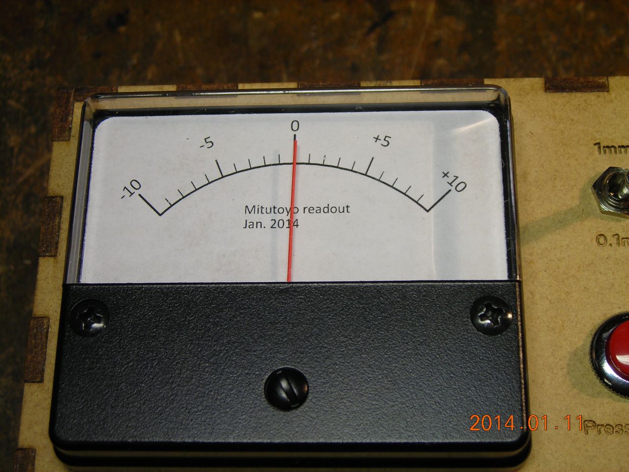
Some pics of the construction of the readout unit. The box is made from laser-cut hardboard, glued together with PVA. Front-panel controls include a zero button and a range select switch (±1mm or ±0.1mm). The meter is adjusted so that the needle is in the center when zeroed. Power comes from a 12V wall adapter - there is a small 78L05 regulator to provide the 5V supply for the logic. Connectors on the side are for the gauge and RS232 serial interface.
 |
 |
 |
 |
 |
 |
 |
 |
 |
 |
 |
 |
 |
 |
 |
 |
 |
 |
 |
 |
| ▲ Electronics |