| ▲ Vacuum |
I thought it would be really nice to make a discharge tube with the cathode in the shape of some letters, a bit like a Nixie tube. I realised it would be possible to make a cathode from something like bent wire or thin sheet. For a vacuum envelope, I decided to use a standard 24mm test tube and attach a bulb base for an electrical connection. I also chose argon as the fill gas, since neon is expensive. Quite a few stages in the construction require a glass lathe with synchronous spindles - I ended up making one, and it's documented here. All glass cutting is done with the scratch and heat method. When cutting off the base from lightbulbs, I leave the vacuum inside so it holds the two parts together once the crack goes through the glass.
Initially, I made up a rough cathode from some 0.7mm steel wire (note that I didn't actually have any bare steel wire, so I had to burn the zinc off a piece of galvanised stuff, which turned out to be a bad idea later on). At first, I tried a planar mesh anode, made from some aluminium insect screen. The anode and cathode are held relative to each other using sheet-mica spacers. This was a fortunate discovery - it turns out the sheet mica is widely available as windows for stoves (e.g. http://stovemica.co.uk/) and that it's also possible to cut it nicely with a CO2 laser cutter.
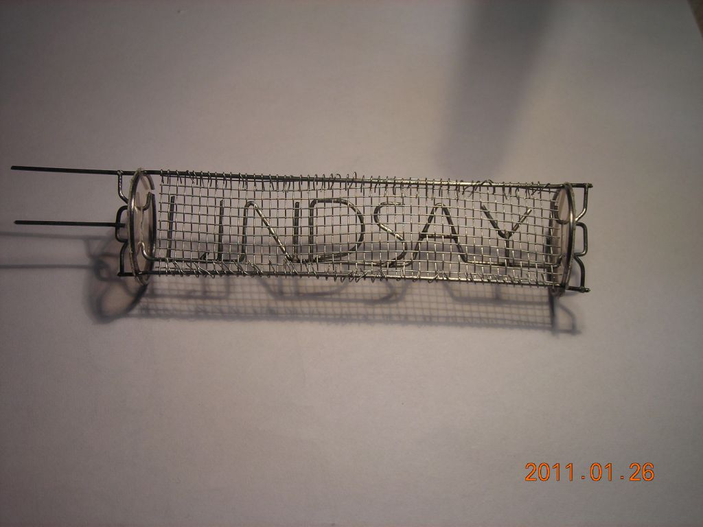
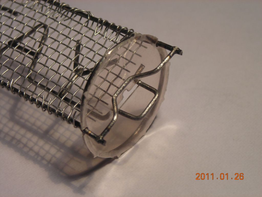
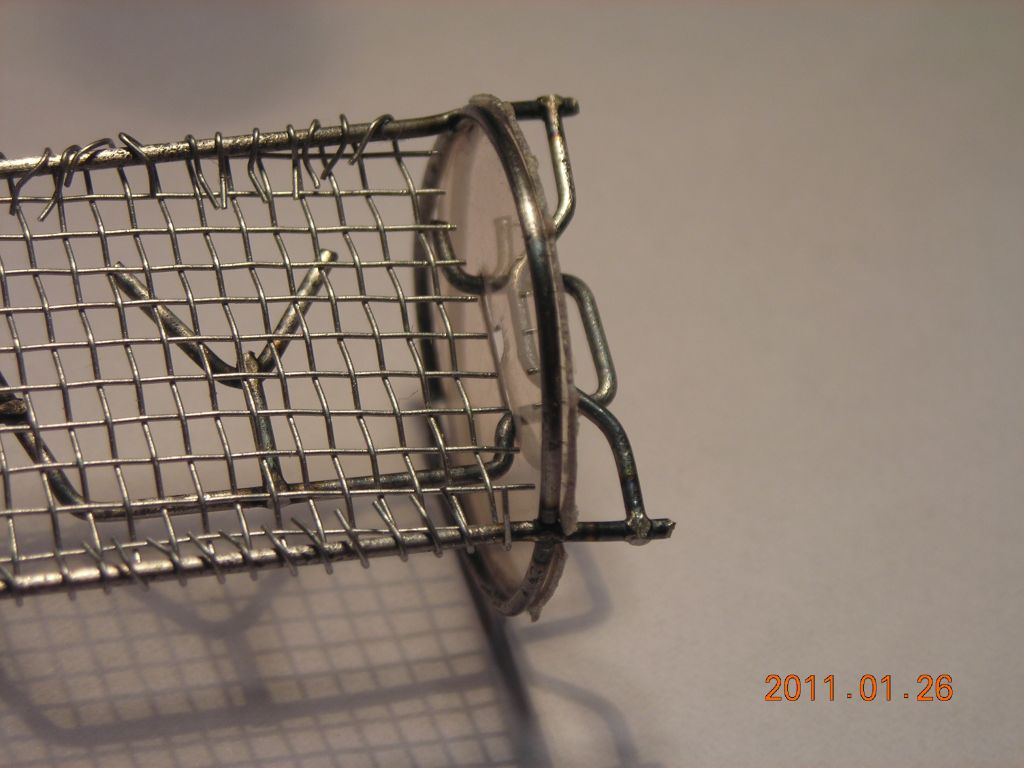
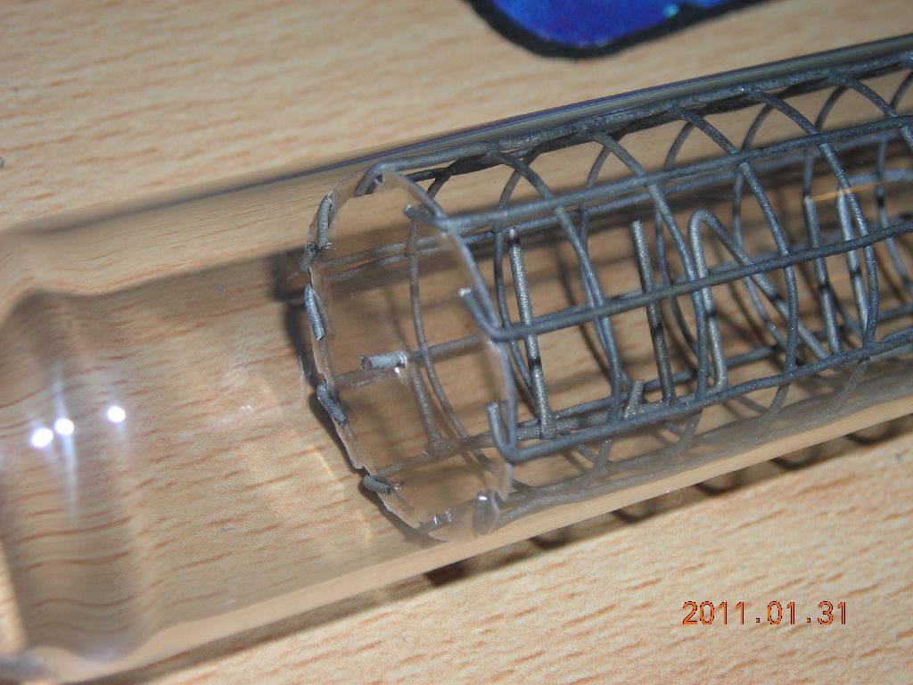
Although the planar anode resulted in a discharge, the cathode glow preferred to stick to one small area and it was impossible to obtain a glow covering the whole cathode. I discovered that using a cylindrical mesh anode ensured a uniform cathode glow at lower currents, and also made it possible to mount the cathode nicely using mica spacers. Lacking a finer-pitch mesh, I used ¼"-pitch welded mesh. The mica spacers are held in place using the bent-over ends of the mesh wires.
 First attempt - wire cathode and fine-mesh planar anode |
 Closeup of mica end spacer |
 |
 Looking edge-on |
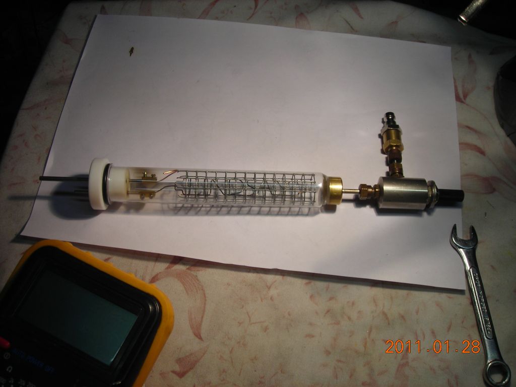 Small vacuum chamber based on a test tube. This is useful for testing the cathode. Gas inlet at right, vacuum on left. |
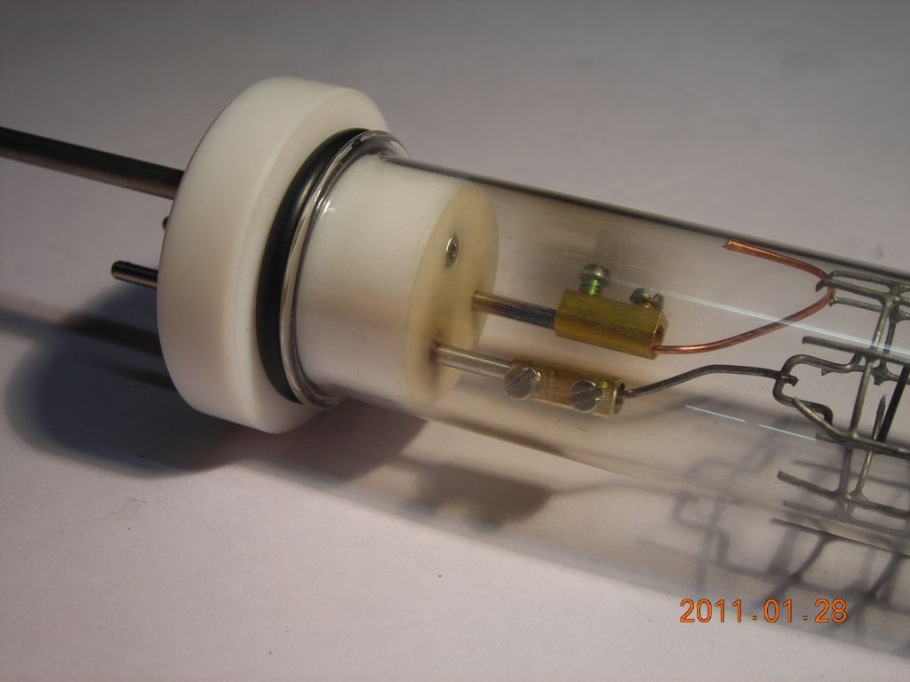 Closeup showing the electrical and gas connections. The white plug is PTFE and is sealed to the rim of the test tube with an O-ring. The electrical feedthroughs are 2mm steel rod press-fitted into the PTFE. |
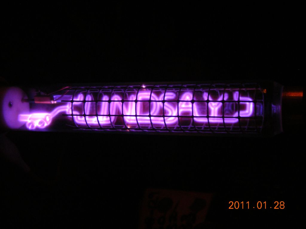 Nice uniform glow from the wire cathode |
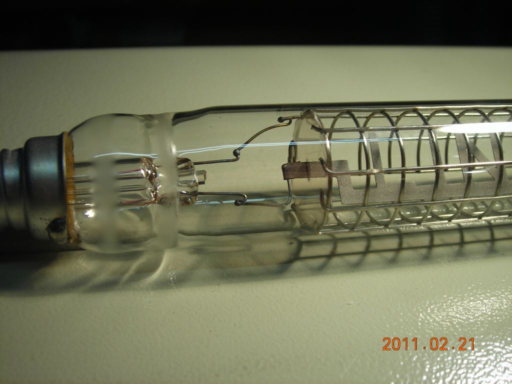
 The electrodes sealed into an envelope. The base is from a standard Edison screw (ES) reflector bulb. Reflector bulbs are good because they have a cylindrical bit of glass near the cap. |
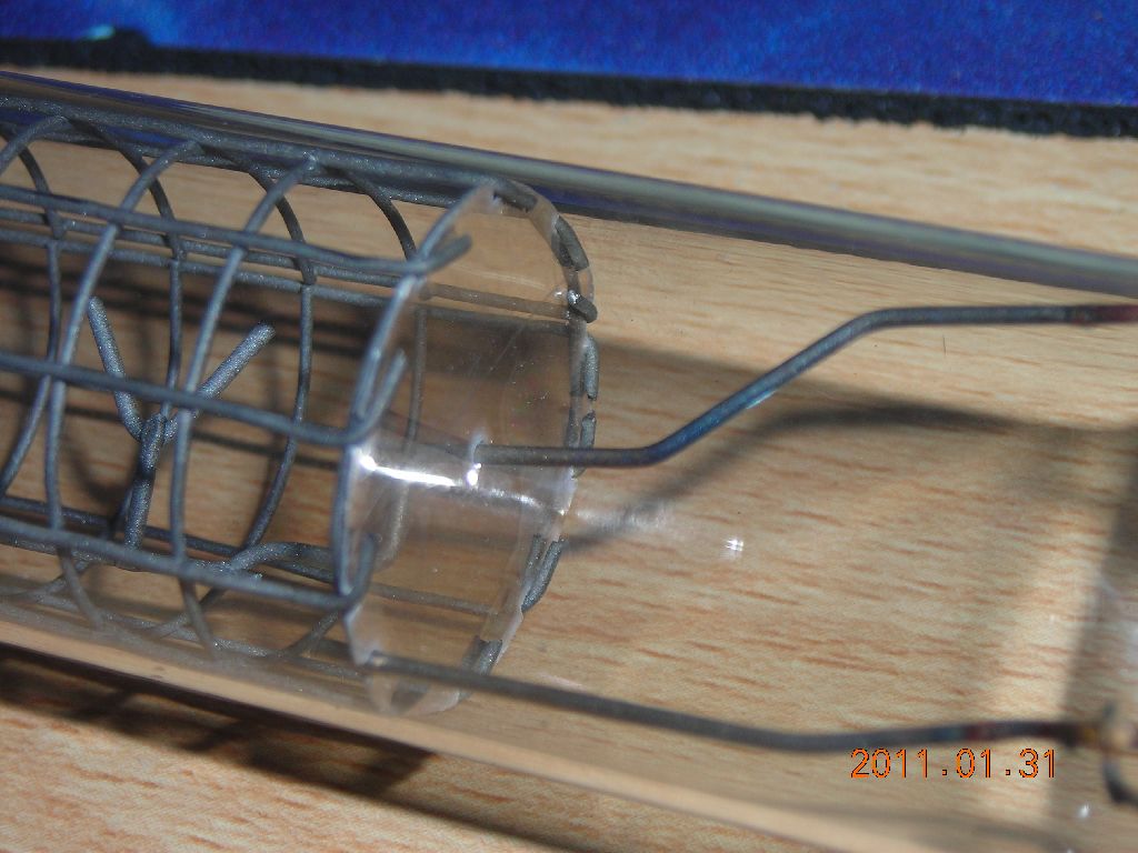
 Closeup of end showing how the mica is held |
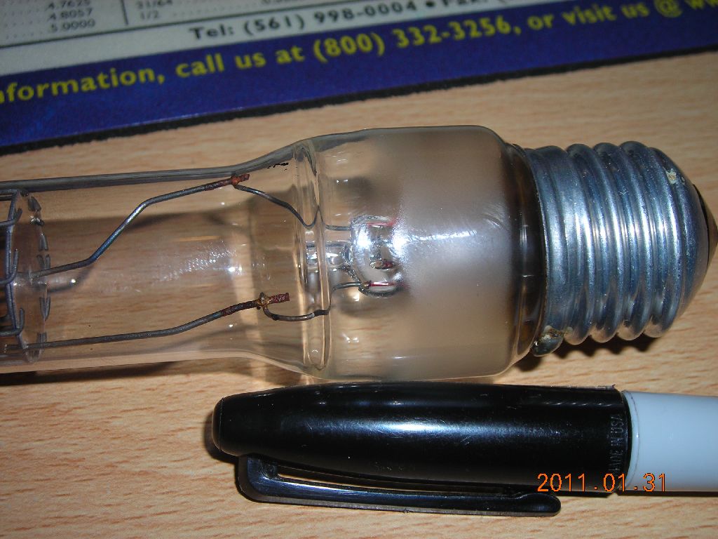 I couldn't managed to spot-weld the lamp lead-in wires to the steel electrode wires, so I silver-soldered them. Not the best! |
 Mockup of the mica insulator with a piece of cardboard |
 The other mica insulator in place |
All this looked good, so I decided to try making a sealed-off unit using the exisiting construction.
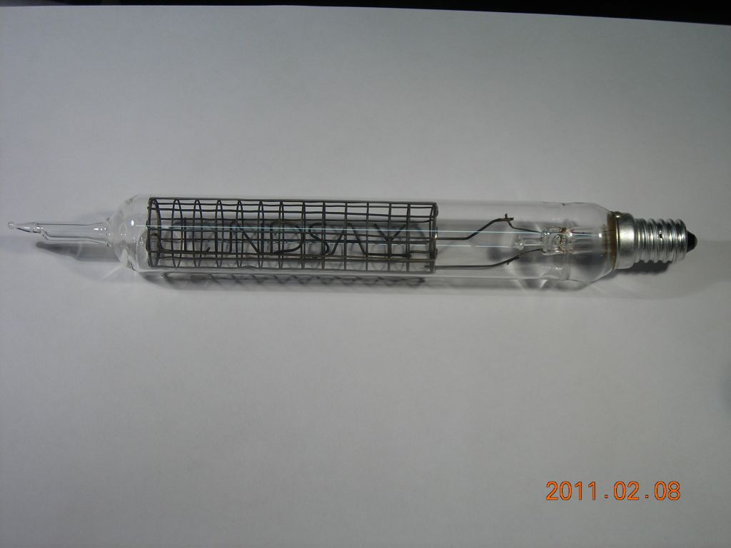
I got my hands on some R50 reflector bulbs, which have a small Edison screw base (SES or "E14") and, amazingly, have a glass diameter of 24mm near the cap, which is an ideal match to the test tubes! I used the same electrode assembly as before. It was evacuated, filled with argon to some unknown pressure (sufficient to give about 1mm thickness of cathode glow) and sealed off. Note that I made no attempts at bakeout or cleaning with this tube.
It lit up nicely, striking at around 280V and requiring around 30mA to achieve a complete cathode glow coverage. However, after only 10 minutes running at 30mA, the minimum required current had risen to nearly 45mA and was steadily climbing. Subsequent investigation revealed that the cathode was running nearly red-hot (I would estimate 500-600°C) and that the remaining zinc and other impurites in the wire were coming out and messing up the vacuum. Hardly surprising! I also discovered that the seal-off had cracked, since I neglected to flame-anneal it.
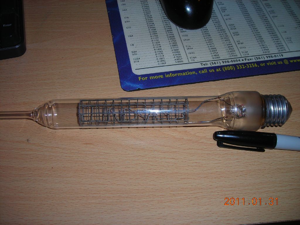
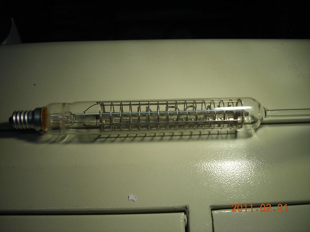
 Overall, sealed-off tube. |
 Closeup of seal-off |
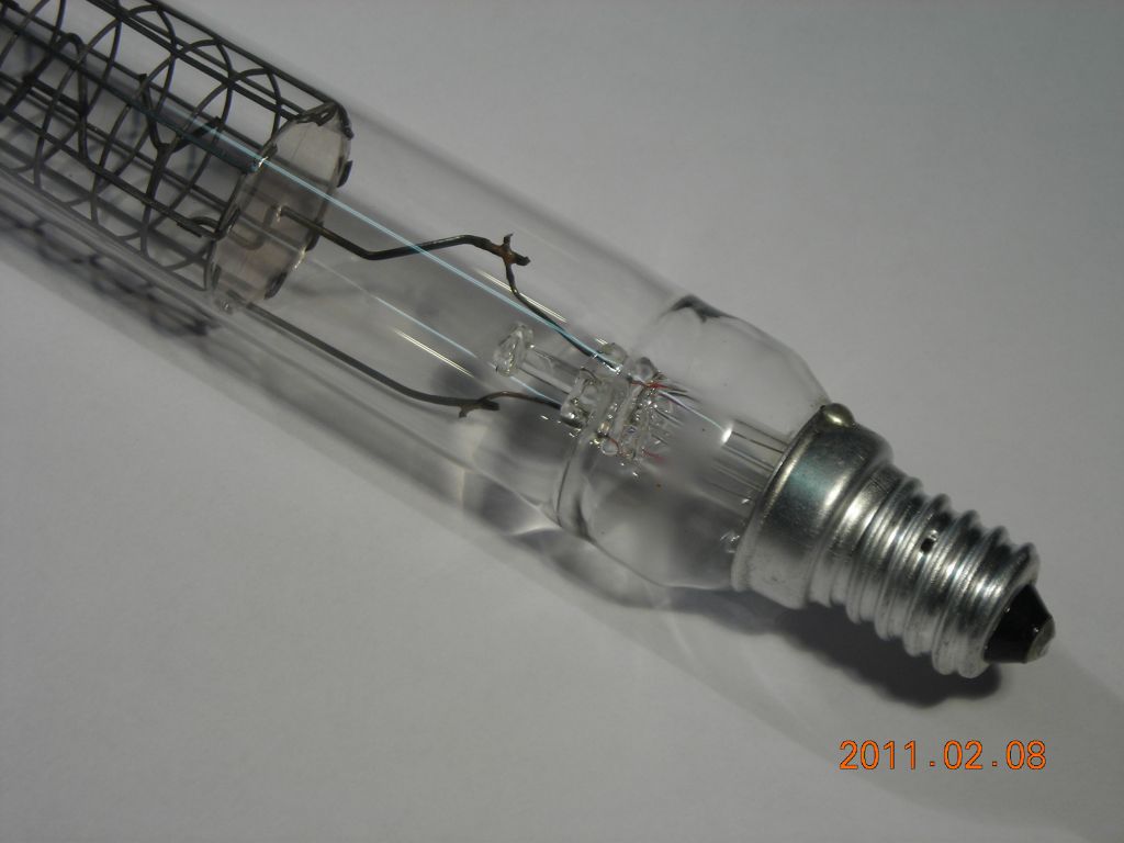 Closeup of lamp base. |
 Glowing, sealed-off. |
 Alas, it's not neon - simply Photoshop! |
For the next attempt, I cleaned things up considerably.
I got hold of some nice stainless-steel mesh from http://www.meshdirect.co.uk/ and decided to make the cathode from a single piece of etched steel sheet. Rather unfortunately, the only thin (0.25mm) steel sheet I could find was a biscuit-tin lid! This, of course, was tin-plated and painted on one side, so I had a fun half-hour sandblasting and dissolving the tin off with nitric acid. The cathode was electrolytically etched from the steel sheet using a double-sided mask made from self-adhesive vinyl film which was laser-cut. I just etched it in a salt solution at about 1A for ½hr.
Instead of soldering the electrodes to the lamp lead-in wires, I had to find a better way of joining them. After a bit of experimentation, I found it was possible to use a very brief pulse from the TIG welder to fuse the ends of the wires (for more info, see the page on pulse arc welding with the TIG). It works great for wires, and also for the flat sheet of the cathode, if it's folded over around a wire first. What's more, the joint can be made while the pieces are on the glass lathe, avoiding having to bend the wires to fit later.
This time, when I was preparing to seal it off, I ran the tube at a very high current (~80mA), alternating between normal and reverse polarity, to burn off any gunk on the electrodes. I wrapped the tube in some glass wool and managed to get it to heat up to around 150°C, holding it there for ½hr or so. Before sealing it off, I heated the area around the seal-off tube to outgas it, pumped it down and re-filled it with argon, and then sealed it off, making sure to flame-anneal the seal-off itself.
This tube is a lot happier and glows nicely at around 20mA current.
 Cathode etched from 0.25mm steel sheet. Surface is sandblasted to clean it. |
 Envelope and base on glass lathe, electrodes welded to lamp wires, ready to seal the envelope. |
 Finished tube, before pumpout |
 Closeup of join between test tube and lamp base |
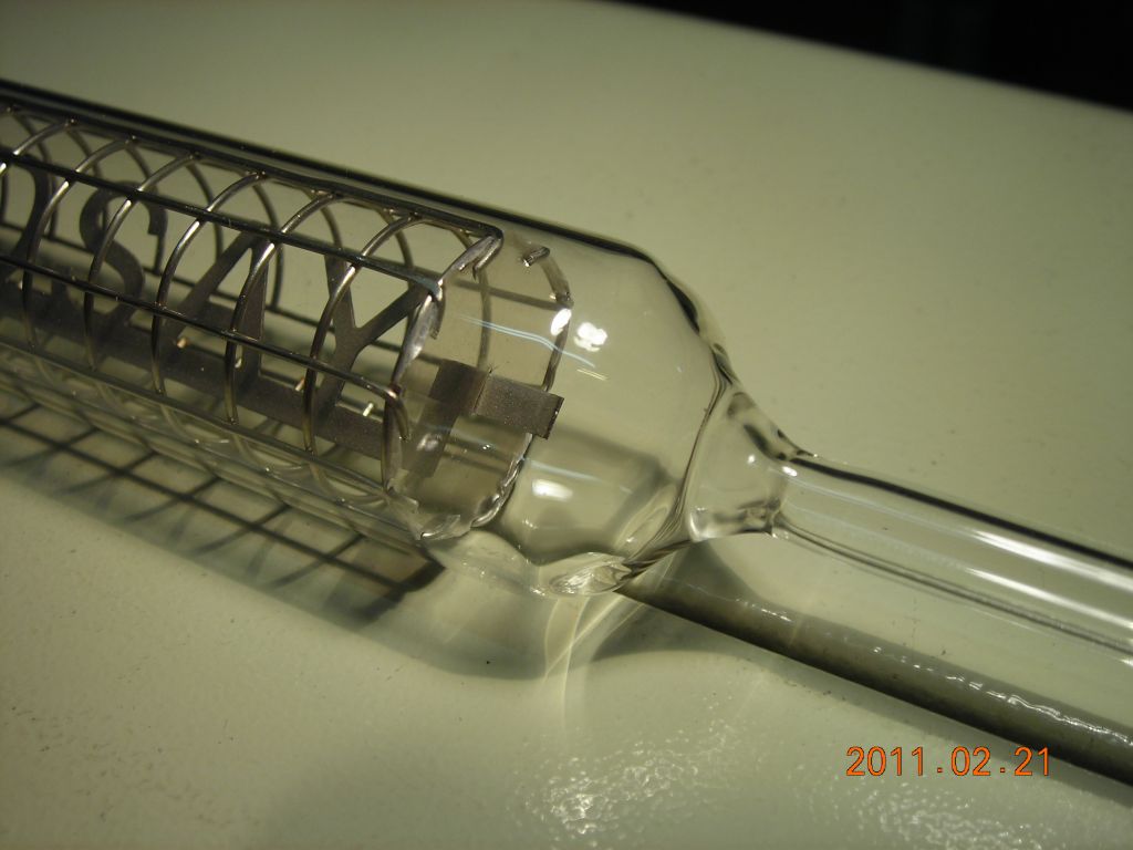 Closeup of pumpout tube join |
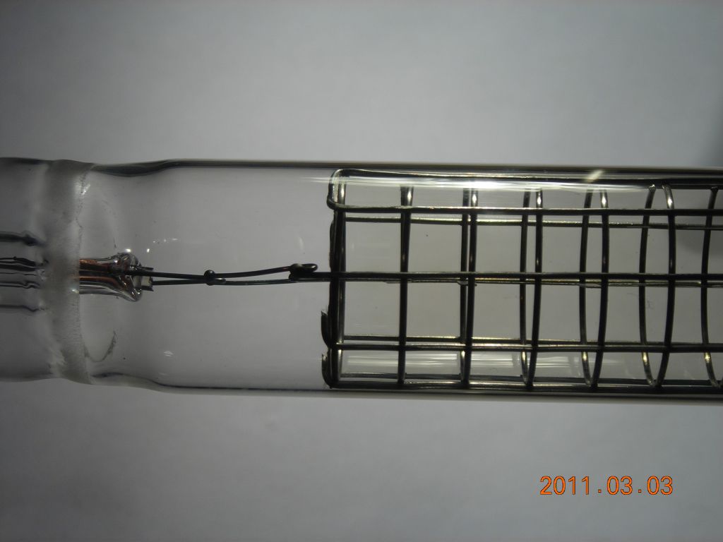
 Nice shot of the onverall tube, after sealoff |
 Really big picture of the electrical end. You can see the welds clearly. |
 Here it is running! Tube is dropping about 230V at 20mA. |
I was a little apprehensive at first of just how long the tube would run. I set it up and recorded the breakdown voltage, minimum current required for a complete cathode glow, and the voltage drop across the tube at this minimum current. The tube was run from a variac with rectifier, smoothing cap and ballast resistor.
Initially, the tube struck at ~260V, required ~14mA minimum current, and dropped around 230V at my chosen operating current of 20mA. I ran it up to a maximum of about 150 hours and things gradually changed over that time, although not significantly. The graphs below show how each of the three recorded variables change over time. I suspect that the biggest reason for the changes is the surface of the cathode - I don't think the gas pressure is changing much because the size of the cathode glow stays pretty constant. The cathode surface, which was initially bright and clean, went dark after about 10 hours of operation. Then, at what must've been around about 50 hours, the dark coating started disappearing from the edges of the cathode, presumably due to sputtering. Eventually, after about 100 hours, the minimum current had risen to more than 20mA and I had to increase the current to get a uniform cathode glow. However, a lifetime of at least 150 hours isn't too bad for a home-made tube, I think. Remember that the "shelf" lifetime will be far, far longer, as it's only the sputtering etc. during operation which results in a limited operational lifetime.
After about 90 hours operation, I took a picture showing a slight darkening of the wall of the test tube from sputtered cathode material. You can just about make it out in the last picture below.
 Striking voltage vs. time |
 Minimum current vs. time |
 Voltage drop at minimum current vs. time |
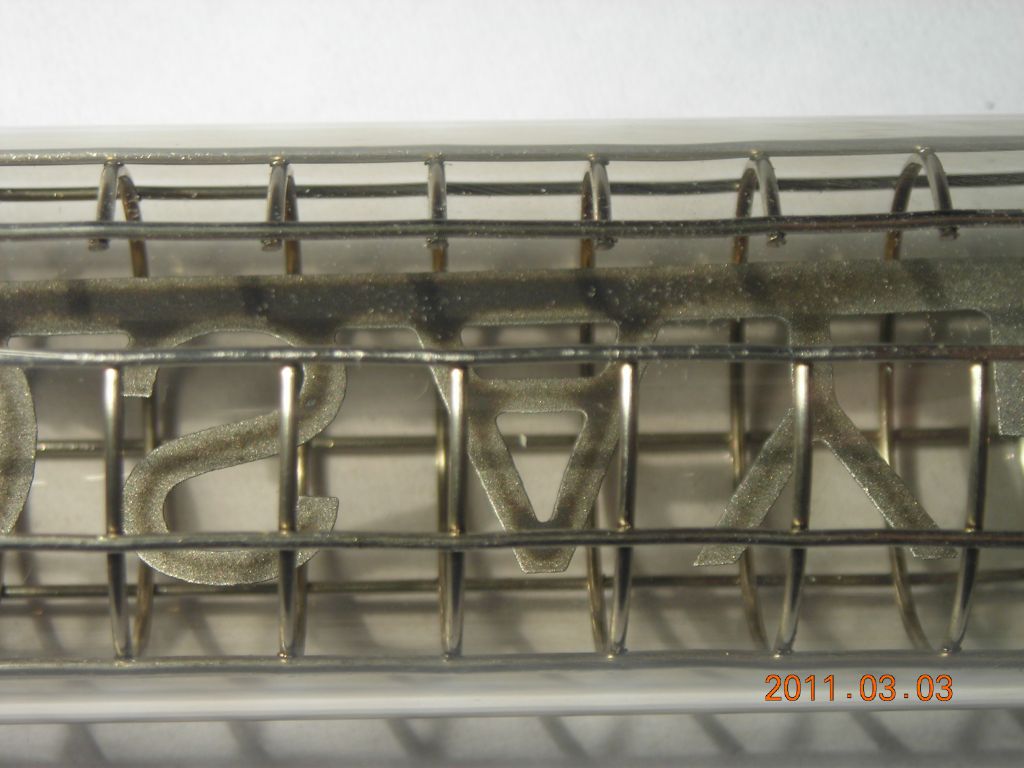 Showing how the dark coating on the cathode has disappeared near the edges (90 hours operation) |
 The tube wall to the right of the mica spacer is slightly darker than on the left as a result of sputtering |
| ▲ Vacuum |