| ▲ Workshop |
This little project was motivated by a couple of things. First, I always needed a footswitch for my welder anyway. Second, I had previously found (see here) that it was possible to do very small welds by using a short pulse. So, I built a little adjustable timer circuit and fitted everything into a nice long diecast aluminium box which had been sitting around for years, waiting for a use.
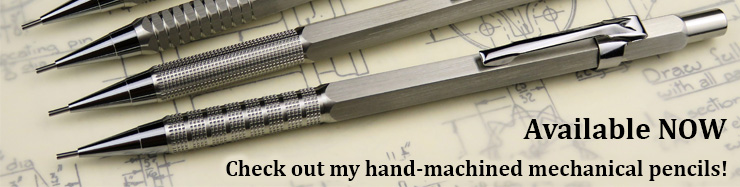
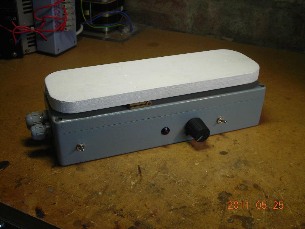
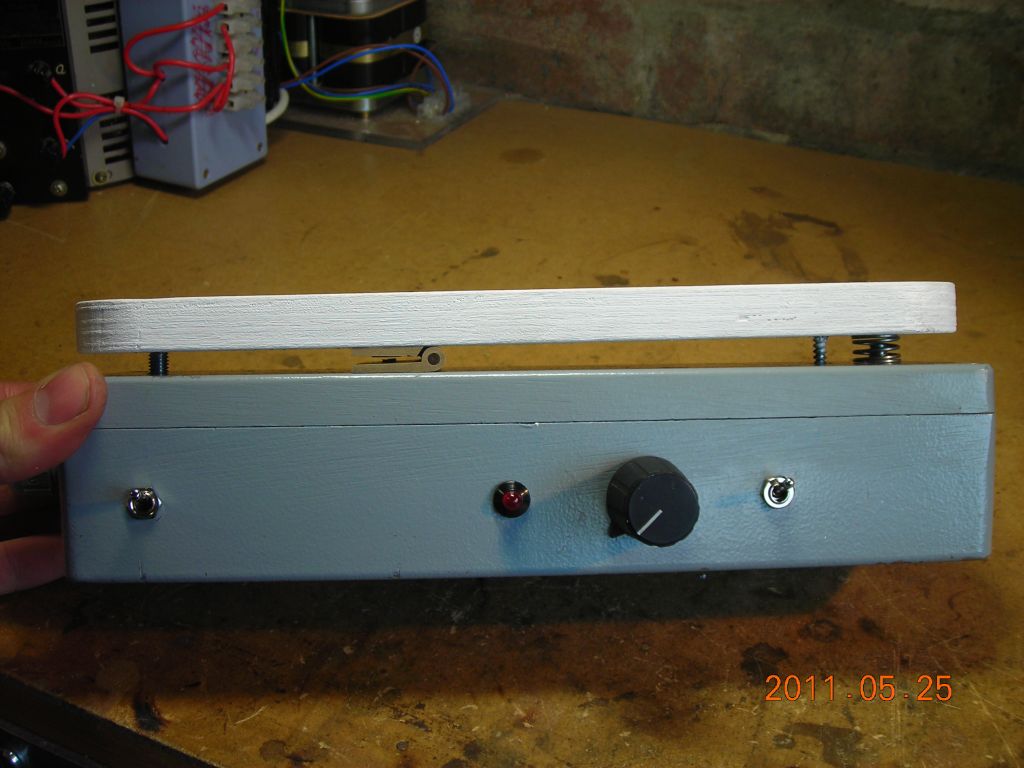
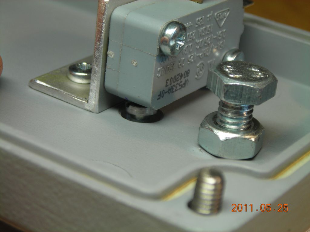
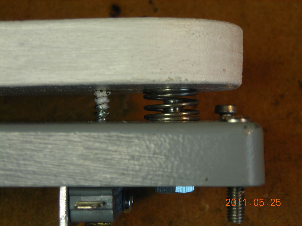
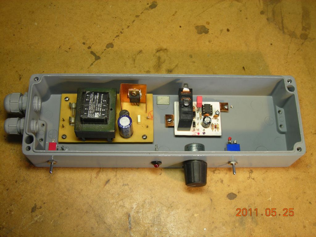
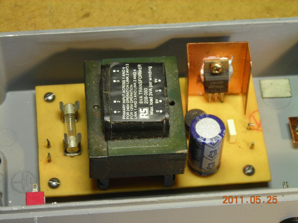
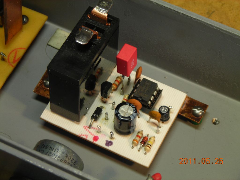
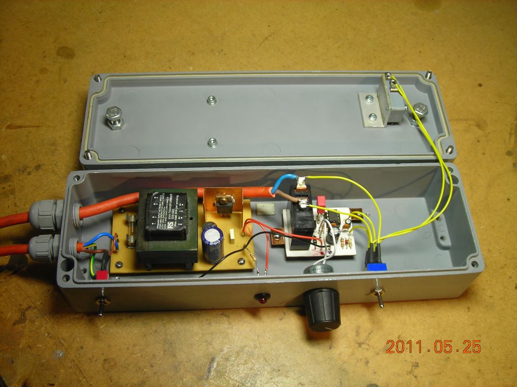
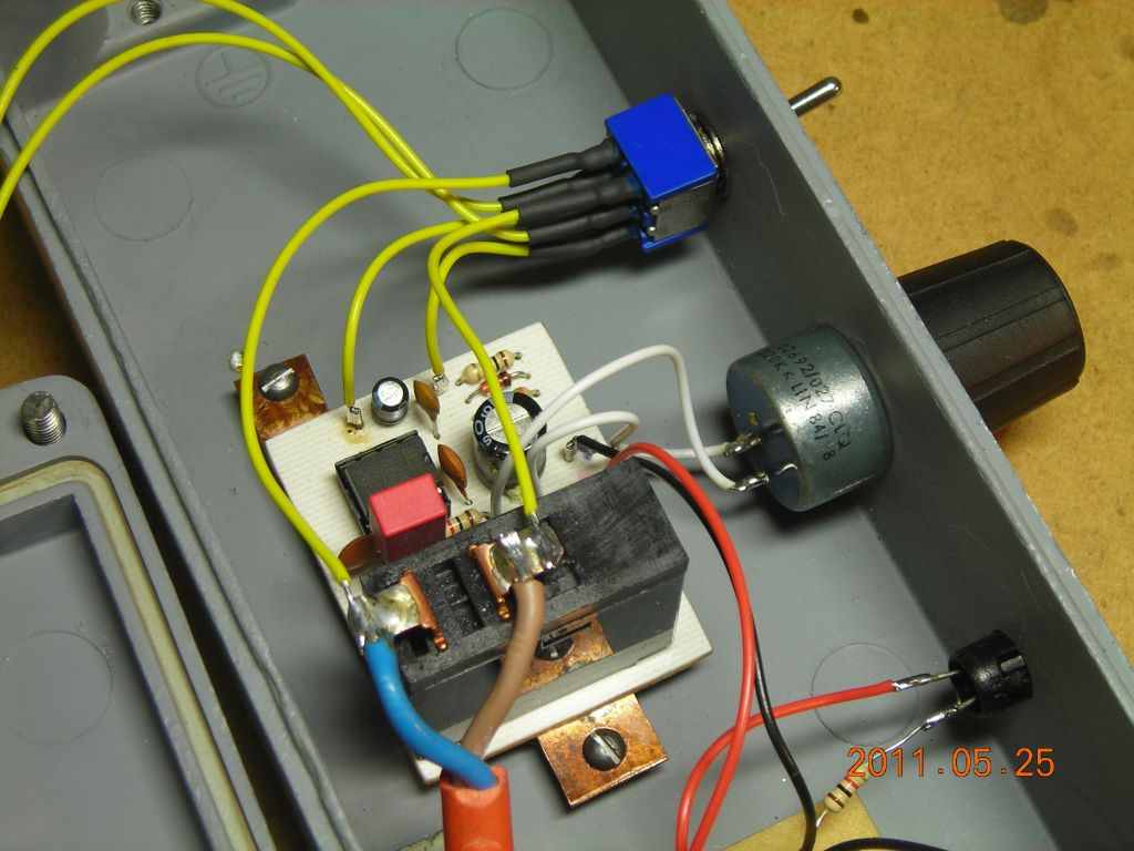
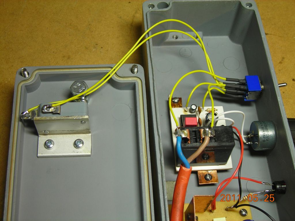
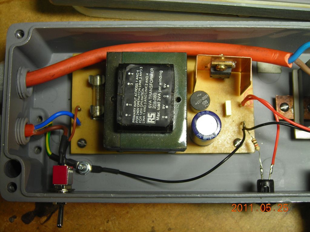
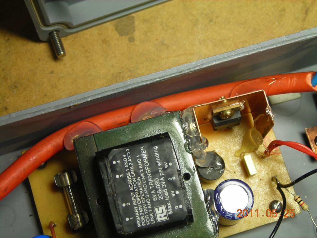
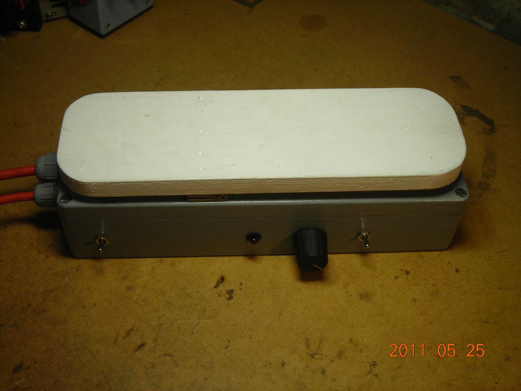
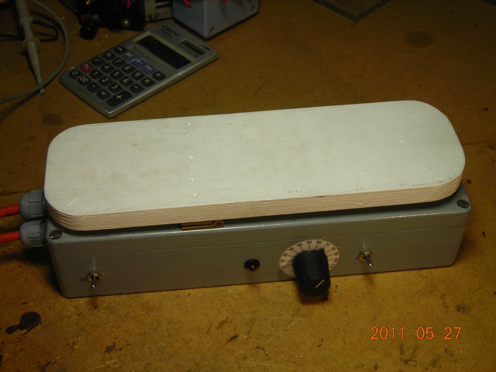
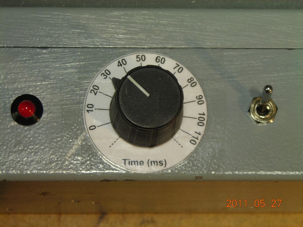
The layout is pretty simple. A large wooden plate is mounted on the top of a box with a hinge, and this triggers a microswitch inside when pressed. Inside, there's a 12V power supply and the timer PCB. This is based on a 555, and is adjustable up to about 100ms. The 555 output drives a relay, whose normally-open contacts go to the trigger switch connection on the welder. A ZIP file containing the circuit of the timer is available here. The timing resistor is a 220kΩ potentiometer, and the capacitor is a 470nF polypropylene. This gives up to about 110ms maximum on time.
Brief comments on the circuit. It's basically just an edge-triggered monostable circuit. R1 and C1 provide some filtering to eliminate the effects of contact bounce in the trigger switch. C2, D1 and R2 differentiate and clip the voltage on C1 and provide a short (few 100ns) pulse to trigger the 555. The output from the 555 drives a 12V power relay from a microwave oven using a BC337 transistor. D2 provides protection agains inductive kick from the relay coil.
As a further refinement, I added a DPDT switch (the one with the yellow wires in the photo) which connects the microswitch to either the timer circuit or in parallel across the relay output contacts, and hence directly across the welder trigger contacts. This allows the footswitch to be used in two modes - timed, where a press of the footswitch initates a brief weld pulse, and continuous, where the weld is on for as long as the footswitch is pressed down.
 |
 |
 |
 |
 |
 |
 |
 |
 |
 |
 |
 |
 |
 |
 |
 |
 |
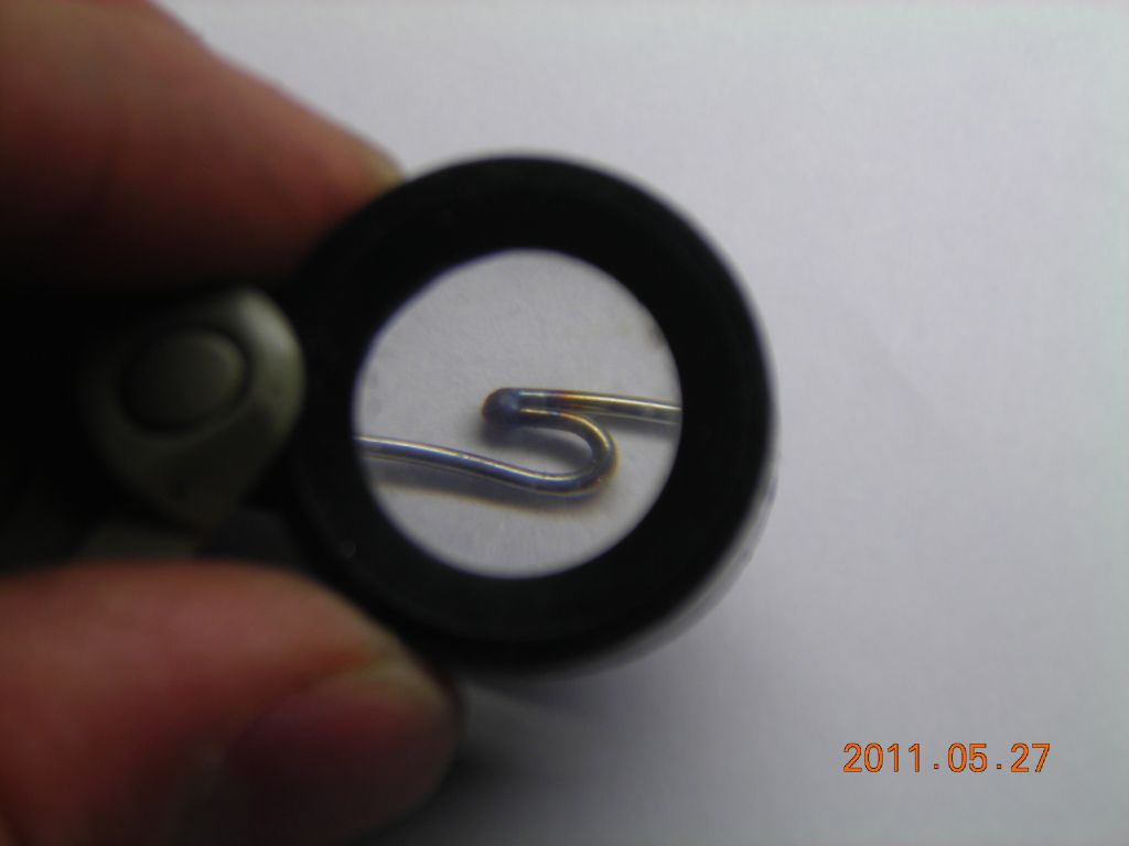
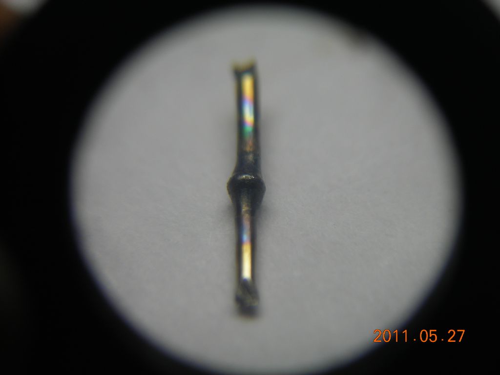
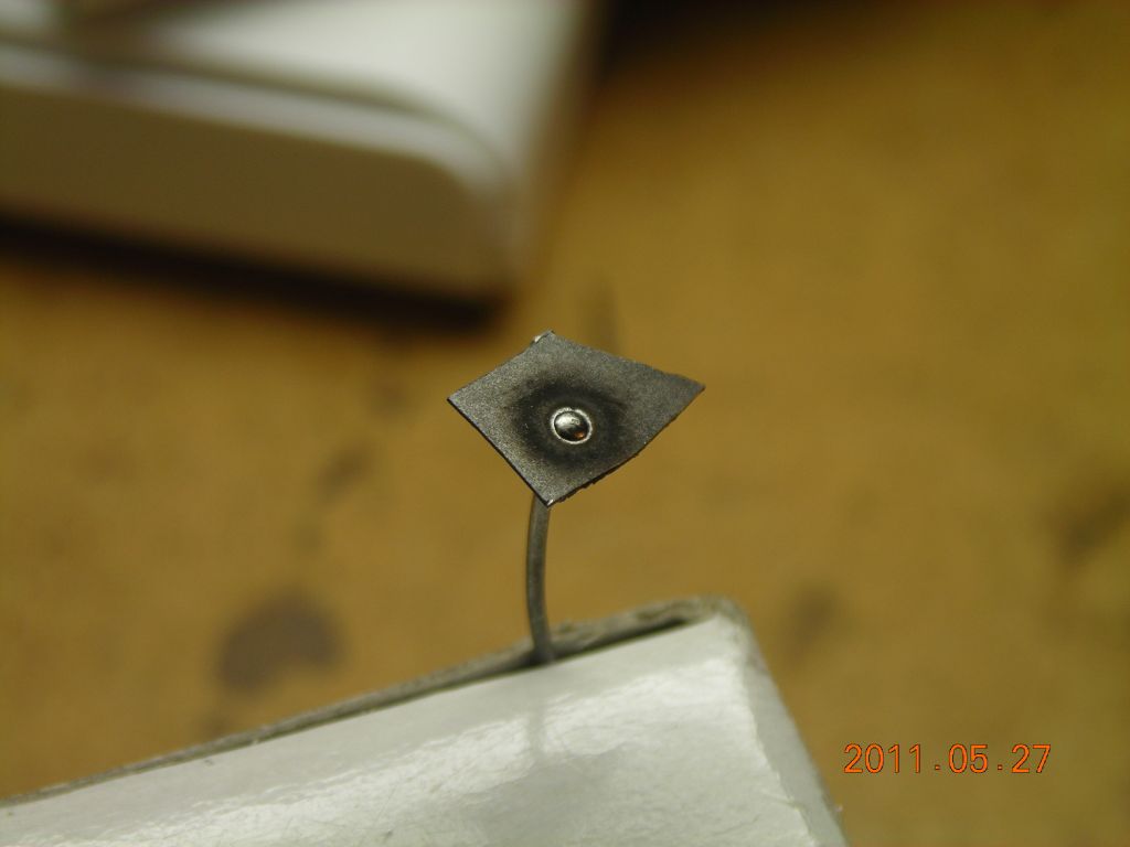
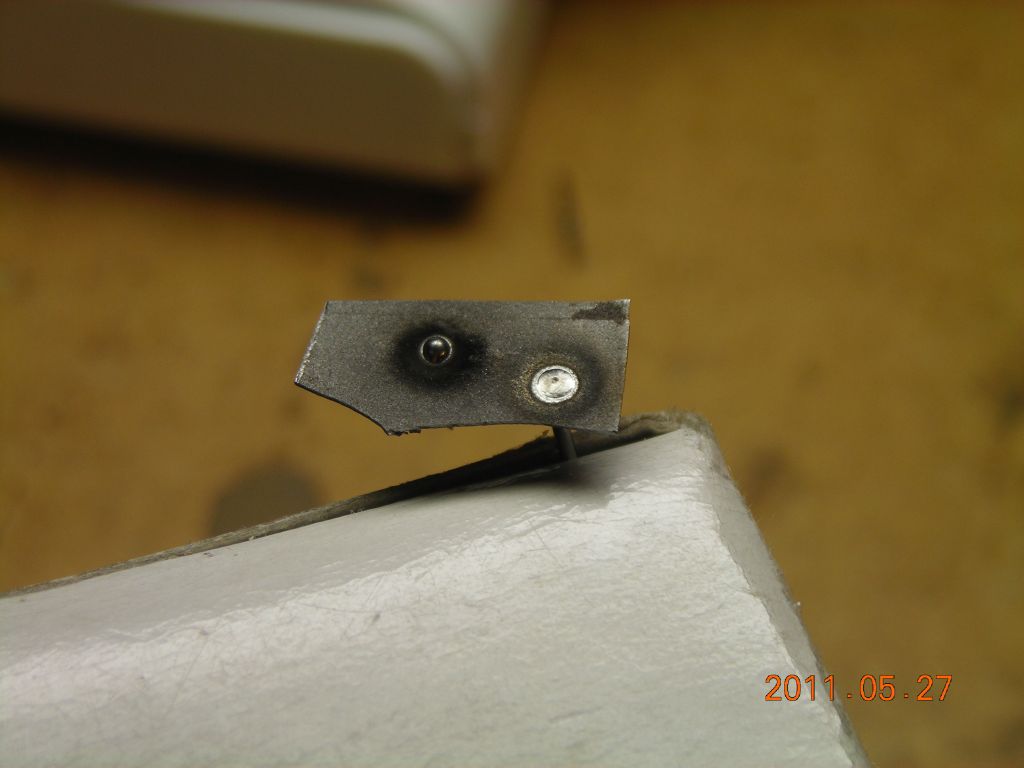
Here's some examples of welds I did with 0.7mm wire. Current is 60A and the pulse time is between 40-70ms, depending on the weld. Gas is turned on manually, since the gas flow can't respond to the short weld time. Joining wires is best done by making a little U-bend in one, and welding the other on as shown in the first photo below. Surface tension keeps the molten droplet on both the wires. Doing a butt join is a lot trickier, since the molten ball tends to move away from the join and break the connection. It is possible though. The last two photos show how a 0.7mm stainless steel wire is welded at right-angles to a 0.25mm steel sheet. A hole is drilled in the sheet first, the wire passed through, and then zapped from above. This melts a ball of metal on the end of the wire, which then fuses with the surrounding sheet metal. If desired, the weld can be sanded down so there's no trace of a lump left.
 |
 |
 |
 |
In conclusion, it's a great way of doing fine welds on small wires and thin plate, ideally suited to the construction of vacuum tube innards.
16/10/11: See here for an example of using the welder to fabricate a current-sense resistor element from some Constantan and copper wire.
28/05/12: This technique can also be used to butt-weld wires using a little jig.
| ▲ Workshop |